Vakuumtooling Neology HF3.pdf - 第32页
Installation instructions Vacuum Tooling Neology (00166109-01) SIPLACE HF3 02/2005 Edition 32 2.5 Pneumat ic d rawi ng 2 Vakuum tooling, pl acement area 1 PUN 6x1 Lenght = Suction nozzle w ith mount Festo 189174-ES G-30-…
Installation instructions Vacuum Tooling Neology (00166109-01) SIPLACE HF3
02/2005 Edition
31
2.4 Conveyor firmware
2.4.1 HyperTerminal
Activate the "Vacuum tooling for VDO Regensburg" program. 2
Use an external computer to connect to the interface cable (RS 232) on the conveyor control via
HyperTerminal. 2
The instructions and program can be found on the enclosed CD. 2
2.4.2 Download the special design conveyor firmware in SITEST
Downloading the special design conveyor firmware T0610515.HEX provided on CD. 2
2.4.3 How the special design conveyor firmware works
The two outputs of the vacuum sensor are scanned by the conveyor firmware. If the two "Lifting
table up“ and "Vacuum established" signals are present, then the placement process is enabled.
After placement there is a further scan to determine whether the vacuum has fully dissipated. The
lifting table cannot be moved down or the PCB moved to the intermediate belt or output belt until
this is true. 2
2
2
2
2
2
2
2
2
2
2
2
2
2
2
Installation instructions Vacuum Tooling Neology (00166109-01) SIPLACE HF3
02/2005 Edition
32
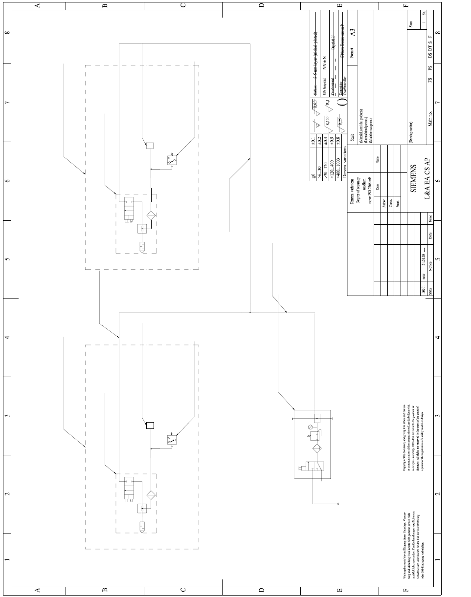
2.5 Pneumatic drawing
2
Vakuum tooling, placement area 1
PUN 6x1 Lenght =
Suction nozzle with mount
Festo 189174-ESG-30-BN-HD-QS
(2)
Service unit
Festo 185719 LFR-1/8-D-MINI-KB
1
2
(2)
2
PUN 8x1 Lenght =
Schmalz air pressure sensor
VS-V-D-PNP
2
PUN 6x1 Lenght =
Vacuum suction nozzle
Festo 162504 VADM-200
Pneumatic diagram SOKO 00166109-01
21.01.05
Pfliegl
Lorenz21.01.05
00166109-01
Neology Vacuum tooling
3 3
3
Vacuum suction nozzle
Festo 162504 VADM-200
1 1
Vakuum tooling, placement area 2
Suction nozzle with mount
Festo 189174-ESG-30-BN-HD-QS
Schmalz air pressure sensor
VS-V-D-PNP
Installation instructions Vacuum Tooling Neology (00166109-01) SIPLACE HF3
02/2005 Edition
33
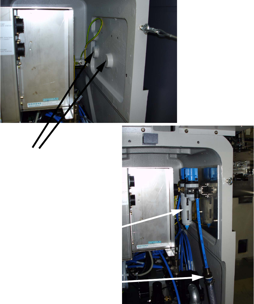
2.5.1 Compressed air supply
Direct connection to the HF pneumatic unit is not possible, since this would exceed the specified
air consumption. An additional maintenance unit must therefore be installed in the pneumatic unit.
The customer must provide an additional compressed air line. 2
The maintenance unit is fitted in the pneumatic unit on a mounting plate. 2
2
Fixing the
mounting plate 2
Additional maintenance unit
in the pneumatic block 1
Additional external
air connection 1