Vakuumtooling Neology HF3.pdf - 第33页
Installation instructions Vacuum Tooling Neology (00166109-01) SIPLACE HF3 02/2005 Edition 33 2.5.1 Compressed ai r supply Direct c onnectio n to the HF pneumat ic unit is not possi ble, si nce this would ex ceed th e sp…
Installation instructions Vacuum Tooling Neology (00166109-01) SIPLACE HF3
02/2005 Edition
32
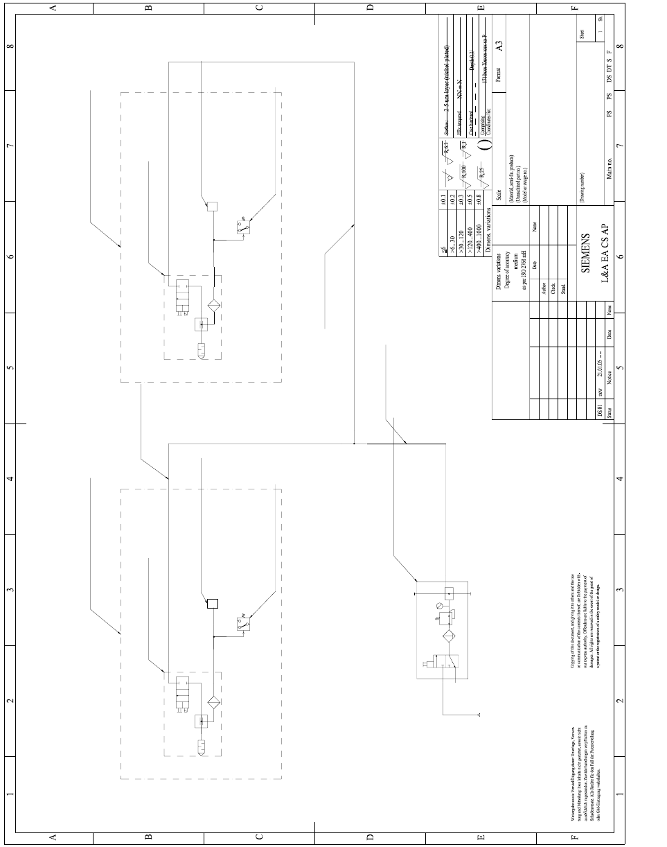
2.5 Pneumatic drawing
2
Vakuum tooling, placement area 1
PUN 6x1 Lenght =
Suction nozzle with mount
Festo 189174-ESG-30-BN-HD-QS
(2)
Service unit
Festo 185719 LFR-1/8-D-MINI-KB
1
2
(2)
2
PUN 8x1 Lenght =
Schmalz air pressure sensor
VS-V-D-PNP
2
PUN 6x1 Lenght =
Vacuum suction nozzle
Festo 162504 VADM-200
Pneumatic diagram SOKO 00166109-01
21.01.05
Pfliegl
Lorenz21.01.05
00166109-01
Neology Vacuum tooling
3 3
3
Vacuum suction nozzle
Festo 162504 VADM-200
1 1
Vakuum tooling, placement area 2
Suction nozzle with mount
Festo 189174-ESG-30-BN-HD-QS
Schmalz air pressure sensor
VS-V-D-PNP
Installation instructions Vacuum Tooling Neology (00166109-01) SIPLACE HF3
02/2005 Edition
33
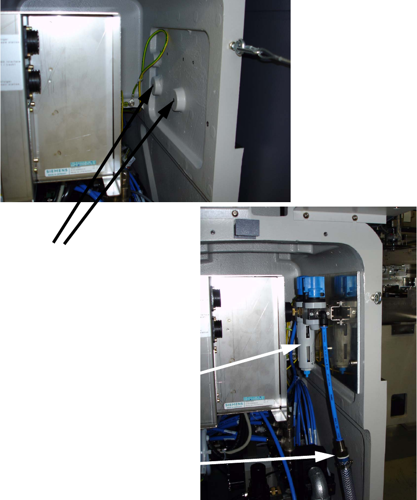
2.5.1 Compressed air supply
Direct connection to the HF pneumatic unit is not possible, since this would exceed the specified
air consumption. An additional maintenance unit must therefore be installed in the pneumatic unit.
The customer must provide an additional compressed air line. 2
The maintenance unit is fitted in the pneumatic unit on a mounting plate. 2
2
Fixing the
mounting plate 2
Additional maintenance unit
in the pneumatic block 1
Additional external
air connection 1
Installation instructions Vacuum Tooling Neology (00166109-01) SIPLACE HF3
02/2005 Edition
34
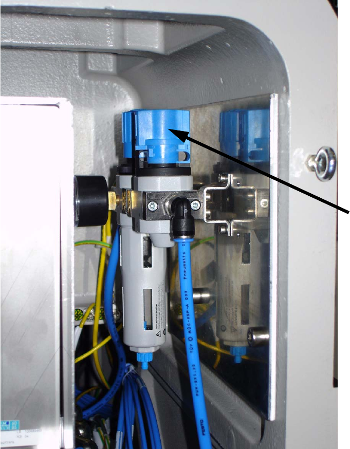
2
2
2
2
2
2
2
Stop valve
on maintenance
unit 2
The set pressure should be between 5.5 and 6 bar. 1