OM-1650-001_w.pdf - 第17页
OM-1650 14 6. Pattern Program 6.3 Placement Data (O Data) When "Mode" in "Unit PCB BBR" is set to "Optional", set "B-X" and "B-Y" in the Placement Data (O Data). [1] &quo…
OM-1650
13
6. Pattern Program
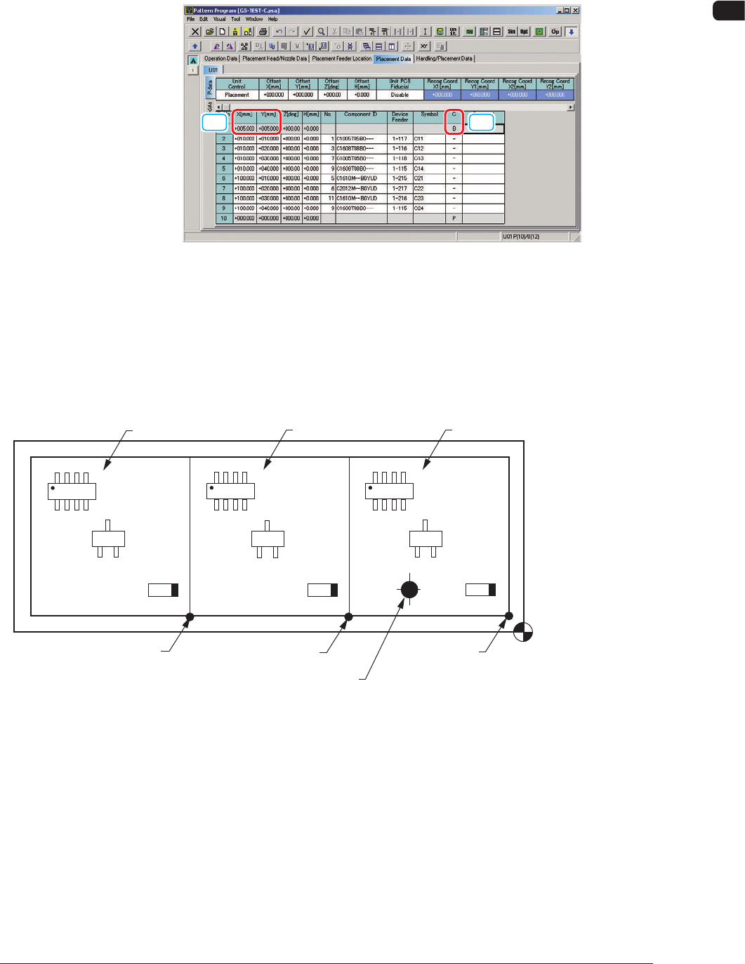
6.2 Placement Data (P Data)
When "Mode" in "Unit PCB BBR" is set to "Normal", set the bad mark
coordinates in the "P-No. 1" step data box in the Placement Data (P Data).
[1] [2]
"Placement Data (P Data)" Tab Sheet F7
[1] X[mm] and Y[mm] in "P-No. 1" Step
Set the coordinates (BX1, BY1) of the bad mark based on the pattern origin.
[2] C for "P-No. 1" Step
Set the control command to "B".
Placement Coordinate
Reference Point
(OX1,OY1)
(OX
2,OY2)
Pattern Origin (OX
3,OY3)
Pattern 1
Bad Mark Affixing Position (BX
1,BY1)
Pattern 2
Pattern 3
F8
1006-001
OM-1650
14
6. Pattern Program
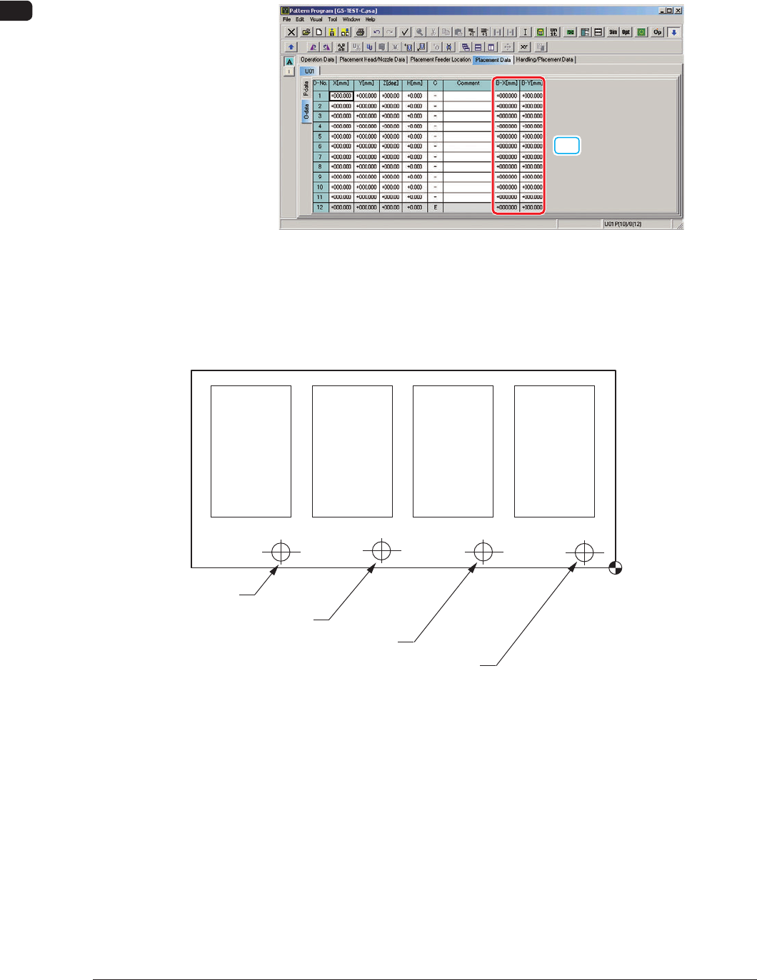
6.3 Placement Data (O Data)
When "Mode" in "Unit PCB BBR" is set to "Optional", set "B-X" and "B-Y" in
the Placement Data (O Data).
[1]
"Placement Data (O Data)" Tab Sheet F9
[1] B-X[mm] and B-Y[mm]
Set the coordinates of each bad mark based on the placement coordinates
reference.
Placement Coordinate
Reference
Bad Mark of Pattern 1
Bad Mark of Pattern 2
Bad Mark of Pattern 3
Bad Mark of Pattern 4
Pattern 4
(B-X
4, B-Y4)
Pattern 3
(B-X
3, B-Y3)
Pattern 2
(B-X
2, B-Y2)
Pattern 1
(B-X
1, B-Y1)
F10
1006-001
OM-1650
15
7. Offset Data
7. Offset Data
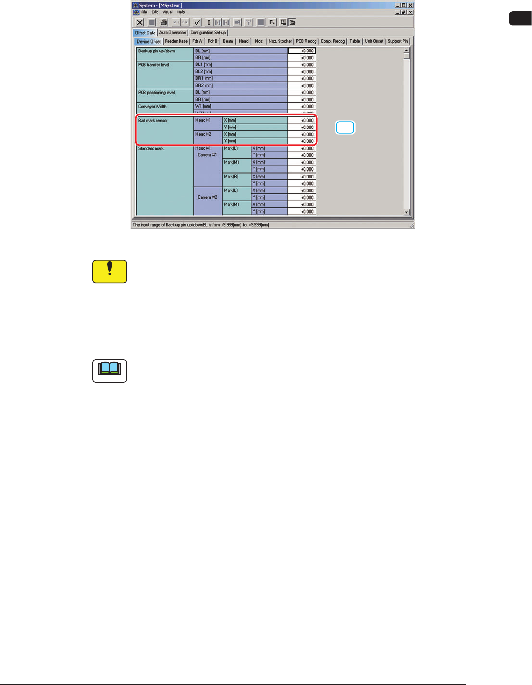
The "Bad Mark Sensor" column is added in the "Device Offset" tab sheet in
"Offset Data".
[1]
"Device Offset" Tab Sheet F11
Notice
They have been adjusted and set before the machine is delivered, so do
not unnecessarily change them.
[1] Bad Mark Sensor
The deviation between the designed position and actual position of the bad
mark sensor installation is adjusted.
Note
When SIGMA-G4 is used, the Head 1 are not displayed on the screen.
1006-001