5TROUBLESHOOTING_.pdf - 第17页
2.1 Easy Troubleshooting 2.1 Easy Troubleshooting Described below are the simple errors against which general operators can take measures . When a general operator cannot solve a certain problem , contact the superintend…
©
huptir
i
o
Page
2
-
1
2.1
Easy
Troubleshooting
2.1
.
1
Power
Operation
Impossible
2.1
.
2
Reset
Procedure
after
[
EMERGENCY
STOP
]
Button
2.1
.
3
L
/
R
Conveyor
Belt
Disengaged
-
2.1
.
4
P
.
C
.
B
.
Transfer
Error
2.2
Troubleshooting
after
Error
Display
2
-
1
2
-
2
2
-
4
2
-
4
-
1
2
-
5
nnm
-
nn
?
ACP
01
EERCC
2
2.1
Easy
Troubleshooting
2.1
Easy
Troubleshooting
Described
below
are
the
simple
errors
against
which
general
operators
can
take
measures
.
When
a
general
operator
cannot
solve
a
certain
problem
,
contact
the
superintendent
of
the
machine
for
his
advice
.
2.1
.
1
Power
Operation
Impossible
Symptom
(
1
)
Nothing
appears
on
the
touch
screen
.
(
2
)
When
the
[
POWER
ON
]
button
on
the
operation
panel
is
pressed
,
the
ine
is
not
powered
.
mach
:
Powe
Cause
⑴
r
is
not
supplied
from
the
source
.
(
2
)
The
main
air
pressure
is
not
set
to
”
0.39
MPa
(
4
kgf
/
cm
2
)
'
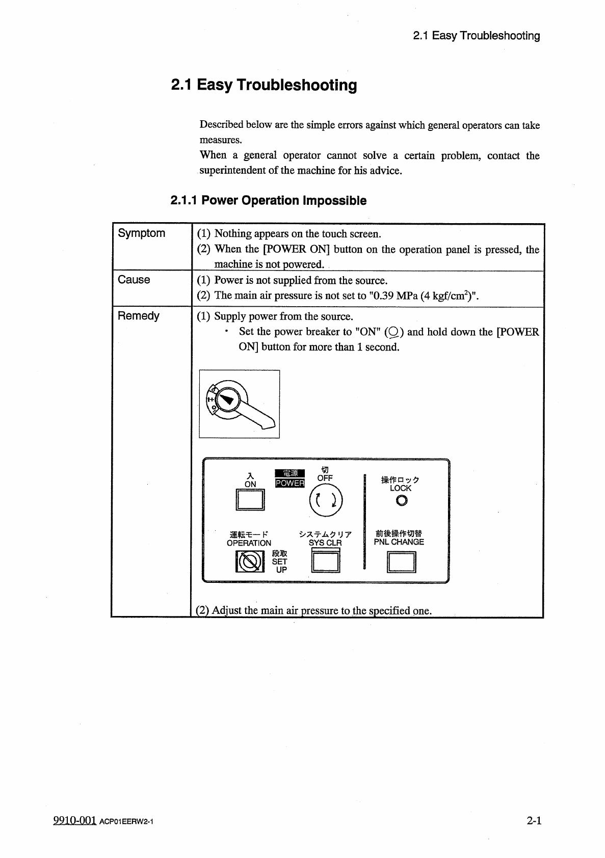
Remedy
(
1
)
Supply
power
from
the
source
.
•
Set
the
power
breaker
to
"
ON
"
(
Q
)
and
hold
down
the
[
POWER
ON
]
button
for
more
than
1
second
.
操作口
:
/
夕
LOCK
o
前後操作切替
PNLCHANGE
亍厶夕
UT
□
(
2
)
Adjust
the
main
air
pressure
to
the
specified
one
.
2
-
1
9910
-
001
ACP
01
EERW
2
-
1
2.1
Easy
Troubleshooting
2.1
.
2
Reset
Procedure
after
[
EMERGENCY
STOP
]
Button
When
an
[
EMERGENCY
STOP
]
button
is
pressed
,
follow
the
steps
below
to
reset
the
machine
to
its
normal
condition
.
Symptom
(
1
)
The
LED
of
the
[
POWER
ON
]
button
is
turned
red
,
indicating
that
the
load
power
supply
is
shut
off
.
Cause
(
1
)
An
[
EMERGENCY
STOP
〗
button
was
pressed
.
Remedy
(
1
)
Check
the
reason
why
the
[
EMERGENCY
STOP
]
button
was
pressed
.
(
2
)
Check
if
some
components
have
dropped
.
If
any
,
remove
them
.
Check
the
areas
under
the
vacuum
nozzles
at
Stations
#
1
through
#
11
.
Especially
,
when
a
component
has
dropped
on
the
component
recognition
section
at
Station
#
5
,
be
sure
to
remove
it
from
the
camera
.
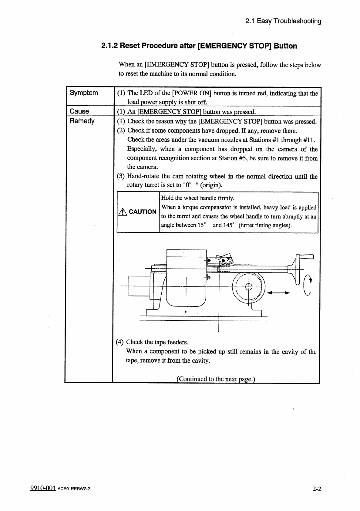
(
3
)
Hand
-
rotate
the
cam
rotating
wheel
in
the
normal
direction
until
the
rotary
turret
is
set
to
"
0
°
”
(
origin
)
.
of
the
camera
Hold
the
wheel
handle
firmly
.
When
a
torque
compensator
is
installed
,
heavy
load
is
applied
to
the
turret
and
causes
the
wheel
handle
to
turn
abruptly
at
an
angle
between
15
°
and
145
°
(
turret
timing
angles
)
.
A
CAUTION
rpzD
c
(
4
)
Check
the
tape
feeders
.
When
a
component
to
be
picked
up
still
remains
in
the
cavity
of
the
tape
,
remove
it
from
the
cavity
.
(
Continued
to
the
next
page
.
)
9910
-
001
ACP
01
EERW
2
-
2
2
-
2