5TROUBLESHOOTING_.pdf - 第31页
2.2 Troubleshooting after Error Display ( C ) ( Display A ) • ( Display B ) • ( Cause ) • ( Remedy ) Order Code ( Display A ) THE COMP . PLACEMENT LEVER C ( Display B ) THE STRUCTURE OF COMP . PLACEMENT LEVER WAS NOT ACT…
2.2
Troubleshooting
after
Error
Display
(
C
)
(
Display
A
)
•
(
Display
B
)
•
(
Cause
)
■
(
Remedy
)
Order
Code
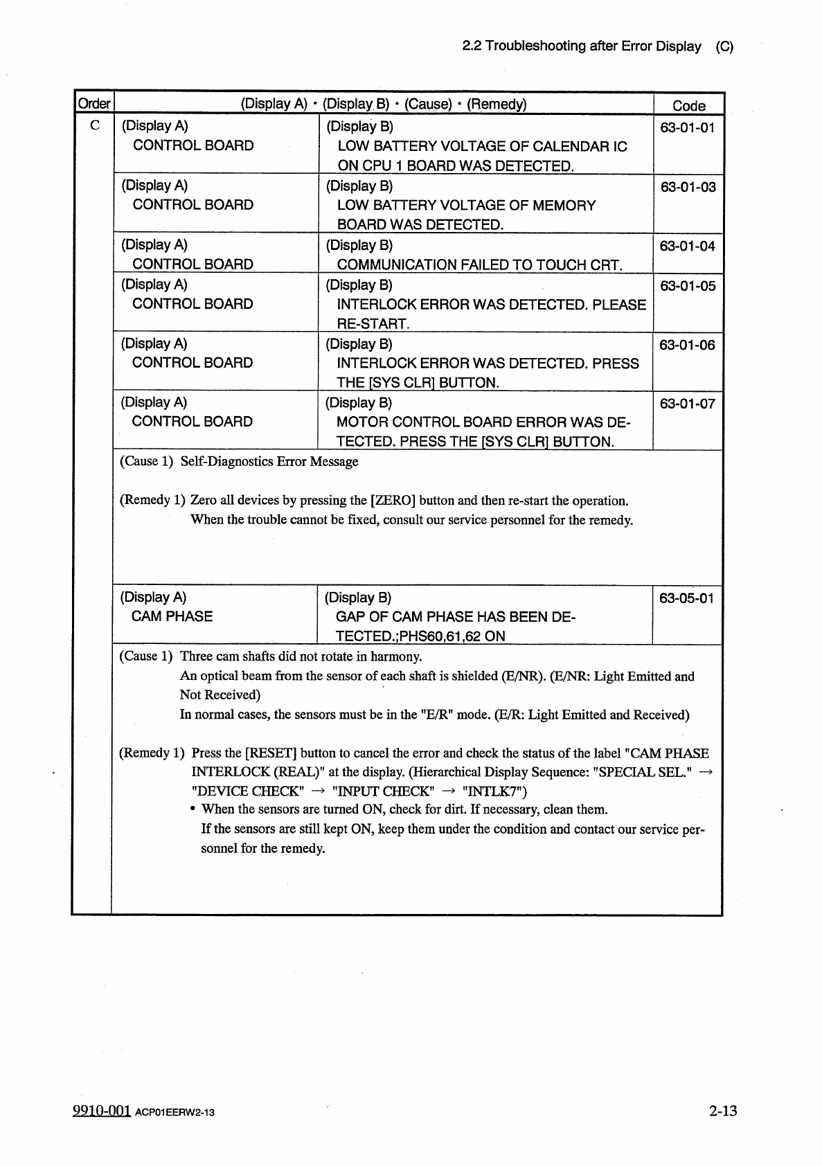
(
Display
A
)
CONTROL
BOARD
C
(
Display
B
)
LOW
BATTERY
VOLTAGE
OF
CALENDAR
1
C
ON
CPU
1
BOARD
WAS
DETECTED
.
63
-
01
-
01
(
Display
A
)
CONTROL
BOARD
(
Display
B
)
LOW
BATTERY
VOLTAGE
OF
MEMORY
BOARD
WAS
DETECTED
.
63
-
01
-
03
(
Display
A
)
CONTROL
BOARD
(
Display
B
)
COMMUNICATION
FAILED
TO
TOUCH
CRT
.
63
-
01
-
04
(
Display
A
)
CONTROL
BOARD
(
Display
B
)
INTERLOCK
ERROR
WAS
DETECTED
.
PLEASE
RE
-
START
.
63
-
01
-
05
(
Display
A
)
CONTROL
BOARD
(
Display
B
)
INTERLOCK
ERROR
WAS
DETECTED
.
PRESS
THE
[
SYS
CLR
1
BUTTON
.
63
-
01
-
06
(
Display
A
)
CONTROL
BOARD
(
Display
B
)
MOTOR
CONTROL
BOARD
ERROR
WAS
DE
-
TECTED
.
PRESS
THE
『
SYS
CLR
]
BUTTON
.
63
-
01
-
07
(
Cause
1
)
Self
-
Diagnostics
Error
Message
(
Remedy
1
)
Zero
all
devices
by
pressing
the
[
ZERO
]
button
and
then
re
-
start
the
operation
.
When
the
trouble
cannot
be
fixed
,
consult
our
service
personnel
for
the
remedy
.
(
Display
A
)
CAM
PHASE
(
Display
B
)
GAP
OF
CAM
PHASE
HAS
BEEN
DE
-
TECTED
.
;
PHS
60
,
61
,
62
ON
63
-
05
-
01
(
Cause
1
)
Three
cam
shafts
did
not
rotate
in
harmony
.
An
optical
beam
from
the
sensor
of
each
shaft
is
shielded
(
E
/
NR
)
.
(
E
/
NR
:
Light
Emitted
and
Not
Received
)
In
normal
eases
,
the
sensors
must
be
in
the
nE
/
RH
mode
.
(
E
/
R
:
Light
Emitted
and
Received
)
(
Remedy
1
)
Press
the
[
RESET
]
button
to
cancel
the
error
and
check
the
status
of
the
label
"
CAM
PHASE
INTERLOCK
(
REAL
)
1
’
at
the
display
.
(
Hierarchical
Display
Sequence
:
"
SPECIAL
SEL
”
—
’
’
DEVICE
CHECK
,
•
When
the
sensors
are
turned
ON
,
check
for
dirt
.
If
necessary
,
clean
them
.
If
the
sensors
are
still
kept
ON
,
keep
them
under
the
condition
and
contact
our
service
per
-
sonnel
for
the
remedy
.
"
INTLK
7
”
)
"
INPUT
CHECK
’
2
-
13
9910
-
001
ACP
01
EERW
2
-
13
2.2
Troubleshooting
after
Error
Display
(
C
)
(
Display
A
)
•
(
Display
B
)
•
(
Cause
)
•
(
Remedy
)
Order
Code
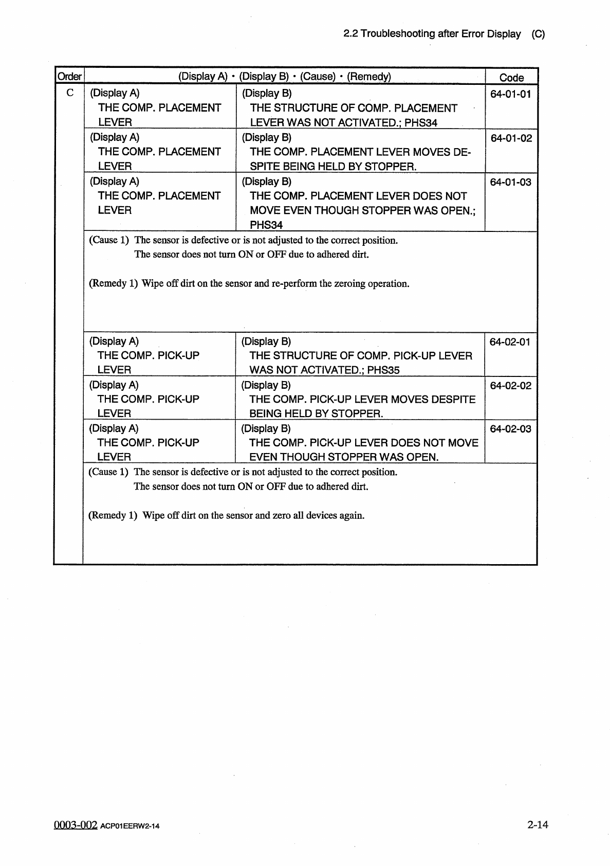
(
Display
A
)
THE
COMP
.
PLACEMENT
LEVER
C
(
Display
B
)
THE
STRUCTURE
OF
COMP
.
PLACEMENT
LEVER
WAS
NOT
ACTIVATED
.
;
PHS
34
64
-
01
-
01
(
Display
A
)
THE
COMP
.
PLACEMENT
LEVER
(
Display
B
)
THE
COMP
.
PLACEMENT
LEVER
MOVES
DE
-
SPITE
BEING
HELD
BY
STOPPER
.
64
-
01
-
02
(
Display
A
)
THE
COMP
.
PLACEMENT
LEVER
(
Display
B
)
THE
COMP
.
PLACEMENT
LEVER
DOES
NOT
MOVE
EVEN
THOUGH
STOPPER
WAS
OPEN
.
;
PHS
34
64
-
01
-
03
(
Cause
1
)
The
sensor
is
defective
or
is
not
adjusted
to
the
correct
position
.
The
sensor
does
not
turn
ON
or
OFF
due
to
adhered
dirt
.
(
Remedy
1
)
Wipe
off
dirt
on
the
sensor
and
re
-
perform
the
zeroing
operation
.
(
Display
A
)
THE
COMP
.
PICK
-
UP
LEVER
(
Display
B
)
THE
STRUCTURE
OF
COMP
.
PICK
-
UP
LEVER
WAS
NOT
ACTIVATED
.
;
PHS
35
64
-
02
-
01
(
Display
A
)
THE
COMP
.
PICK
-
UP
LEVER
(
Display
B
)
THE
COMP
.
PICK
-
UP
LEVER
MOVES
DESPITE
BEING
HELD
BY
STOPPER
.
64
-
02
-
02
(
Display
A
)
THE
COMP
.
PICK
-
UP
LEVER
(
Display
B
)
THE
COMP
.
PICK
-
UP
LEVER
DOES
NOT
MOVE
EVEN
THOUGH
STOPPER
WAS
OPEN
.
64
-
02
-
03
(
Cause
1
)
The
sensor
is
defective
or
is
not
adjusted
to
the
correct
position
.
The
sensor
does
not
turn
ON
or
OFF
due
to
adhered
dirt
.
(
Remedy
1
)
Wipe
off
dirt
on
the
sensor
and
zero
all
devices
again
.
2
-
14
0003
-
002
ACP
01
EERW
2
-
14
2.2
Troubleshooting
after
Error
Display
(
C
)
(
Display
A
)
•
(
Display
B
)
•
(
Cause
)
(
Remedy
)
Order
Code
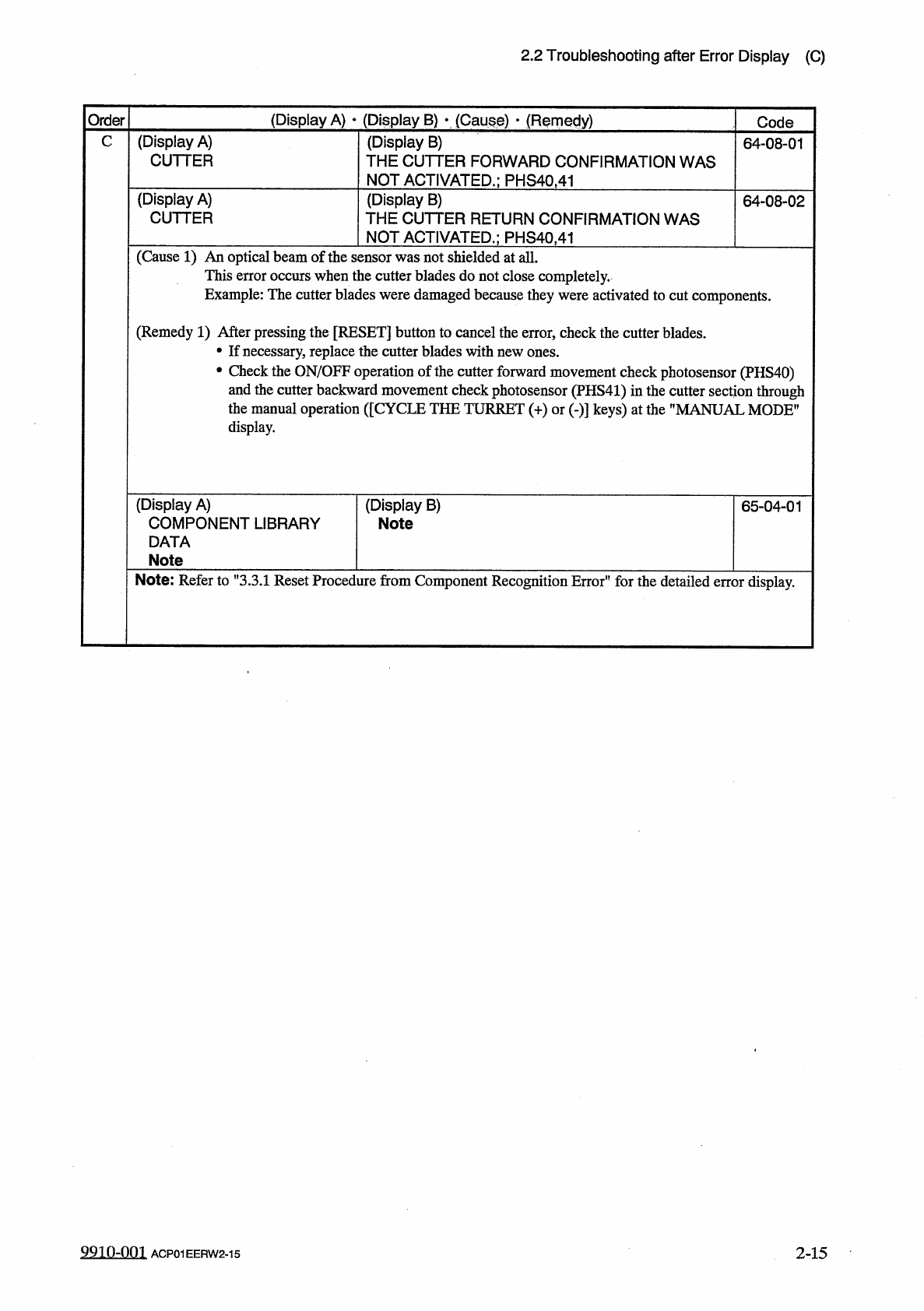
C
(
Display
A
)
CUTTER
(
Display
B
)
THE
CUTTER
FORWARD
CONFIRMATION
WAS
NOT
ACTIVATED
.
;
PHS
40.41
64
-
08
-
01
(
Display
A
)
CUTTER
(
Display
B
)
THE
CUTTER
RETURN
CONFIRMATION
WAS
NOT
ACTIVATED
.
;
PHS
40.41
64
-
08
-
02
(
Cause
1
)
An
optical
beam
of
the
sensor
was
not
shielded
at
all
.
This
error
occurs
when
the
cutter
blades
do
not
close
completely
.
Example
:
The
cutter
blades
were
damaged
because
they
were
activated
to
cut
components
.
(
Remedy
1
)
After
pressing
the
[
RESET
]
button
to
cancel
the
error
,
check
the
cutter
blades
.
•
If
necessary
,
replace
the
cutter
blades
with
new
ones
.
•
Check
the
ON
/
OFF
operation
of
the
cutter
forward
movement
check
photosensor
(
PHS
40
)
and
the
cutter
backward
movement
check
photosensor
(
PHS
41
)
in
the
cutter
section
through
the
manual
operation
(
[
CYCLE
THE
TURRET
(
+
)
or
(
-
)
]
keys
)
at
the
”
MANUAL
MODE
"
display
.
(
Display
A
)
COMPONENT
LIBRARY
DATA
Note
(
Display
B
)
Note
65
-
04
-
01
Note
:
Refer
to
"
3.3
.
1
Reset
Procedure
from
Component
Recognition
Error
"
for
the
detailed
error
display
.
9910
-
001
ACP
01
EERW
2
-
15
2
-
15