Spectrum+Operating+Manual.pdf - 第104页
S2-9 XX X Se ri es Disp ensi n g Syst em IOM Man ual Calibration and Adjus tment 5-28 © 2023 Nordson Corporatio n 5.15 Controlle d Process He at Asymtek ’ s Cont rolled Proc ess Heat (CpH) manage s heat l ev els (e.g ., …
S2-9XXX Series Dispensing System IOM Manual Calibration and Adjustment
© 2023 Nordson Corporation 5-27
5.14.2 Heater Calibration
To calibrate the heaters:
1. In the Fluidmove Main Menu, select
Configuration > Setup Runtime Preferences >
Local Machine Offsets
.
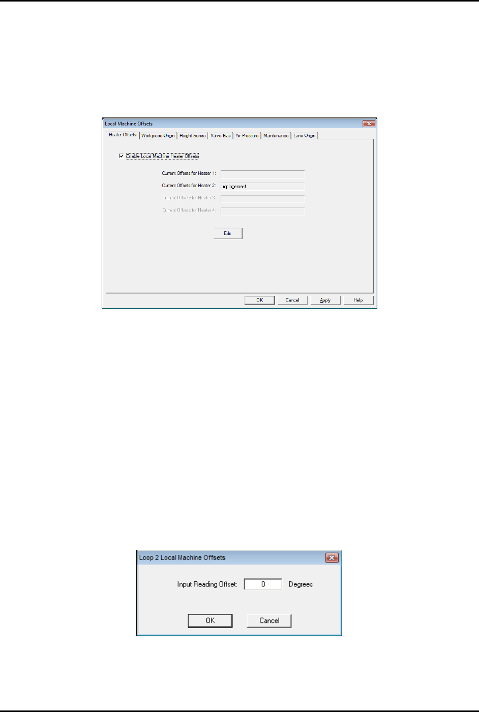
The Local Machine Offsets window opens (Figure 5-32).
Figure 5-28 Local Machine Offsets - Heater Offsets
2. Enable Local Machine Heater Offsets.
A checkmark in the box indicates Local Machine Heater Offsets is enabled. If not
checked, click on the box to enable it.
3. Select
Edit.
4. Select the heater to be calibrated (Heater 1, 2, 3 or 4).
The Heater Control window opens (Figure 5-31).
5. Double-click on the channel name.
6. Enter the temperature offset value in the Input Reading Offset prompt (Figure 5-33).
The temperature offset value is the difference in degrees between the heater setpoint
and actual measured temperature.
Figure 5-29 Input Temperature Offset Value
7. Perform the heater verification procedure again to verify calibration, see 5.14.1 Verifying
Heater Calibration.
S2-9XXX Series Dispensing System IOM Manual Calibration and Adjustment
5-28 © 2023 Nordson Corporation
5.15 Controlled Process Heat
Asymtek’s Controlled Process Heat (CpH) manages heat levels (e.g., warm up, process ramp, cool down,
etc.) with programmable shut-off timers and “step-down” or “no-heat” capability when a part is not
present.
NOTE This procedure applies to systems equipped with impingement heaters and CpH only.
5.15.1 CpH Configuration
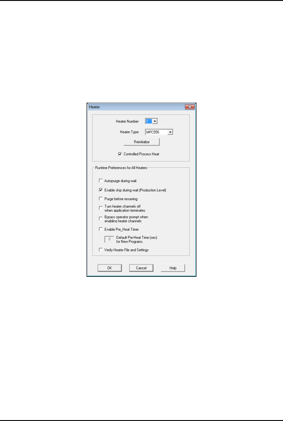
If the dispensing system is equipped with CpH, make sure that option is selected in the Fluidmove Heater
Setup window (Figure 5-34).
Figure 5-30 Heater Setup Window - Controlled Process Heat Enabled
S2-9XXX Series Dispensing System IOM Manual Calibration and Adjustment
© 2023 Nordson Corporation 5-29
To configure CpH:
NOTE CpH can be added to any station and each station is configured independently.
1. In the Fluidmove Main window, select
Tools > Terminal.
2. Select
Heater 2 (Conveyor 1) or Heater 3 (Conveyor 2).
The Heater Control Window opens (Figure 5-30).
3. Double click on the station that you want to configure.
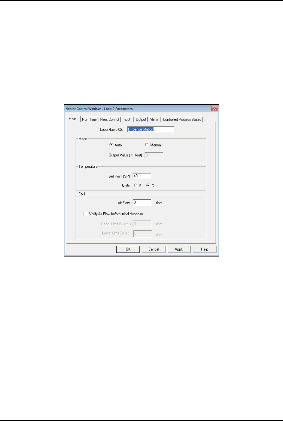
The Heater Control Loop Parameters Window opens (Figure 5-35).
Figure 5-31 Heater Control Loop Parameters Window - Main Tab
4. Enter the desired settings on the Main tab.
5. If you want to set ramp and standby options, go to Step 6, otherwise skip to Step 9.
6. Click on the Controlled Process States tab (Figure 5-36).
7. Enter the desired ramp temperature, airflow, and time.
The ramp temperature is generally higher than the dispense station temperature and is
used to quickly heat a part in the pre-dispense station.
8. Enter the desired standby temperature, airflow, and time.
The standby temperature is generally lower than the dispense station temperature and is
used to reduce energy when a board is not received for a specified amount of time.