Spectrum+Operating+Manual.pdf - 第109页
S2-9 XXX Se ri es Dispensing Sys te m IOM Man ual Calibration and Adjustme nt © 2023 Nordson C orporatio n 5-33 Item Description 1 F lo wmete r Adjustment K nobs 2 I mpingement Air V alv e Figure 5- 36 Adjusting the Impi…

S2-9XXX Series Dispensing System IOM Manual Calibration and Adjustment
5-32 © 2023 Nordson Corporation
5.16 Adjusting Manual Airflow for Impingement Heaters
NOTES This procedure applies to systems equipped with impingement heat and manual flow
controls.
This procedure does not apply to systems configured with optional Controlled Process
Heat (CpH), see 5.15 Controlled Process Heat.
Airflow to impingement heaters is adjusted by turning the applicable flowmeter adjustment knob located
in the lower front cabinet door. Airflow is read on the gauge on the front of the flowmeter (Figure 5-40).
Factors to be considered when determining the airflow include the following:
• Maximum airflow is 4.0 SCFM.
• Size, weight, and securing of the workpiece (high airflow can cause
movement/misalignment).
• Effect of airflow on the time it takes to heat the workpiece to dispensing temperature.
• Effect of airflow on how fast the heat tooling reaches/maintains steady-state temperature.
• Ambient temperature of the dispensing area and its effect on dispensing fluid properties
(pot life, viscosity, cure time).
To adjust the flowmeters (Figure 5-40):
1. Locate the impingement air valve and flowmeters in the front cabinet of the dispensing
system.
Depending on system configuration, there can be up to six (6) flowmeters (pre-queue,
dispense, and post-queue for Conveyor 1 and Conveyor 2).
The pre- and post-queue flowmeters are located below the pre- and post-queue stations.
2. Open the impingement air valve by turning the handle counterclockwise so that it is parallel
with the airline and listen for leaks.
If there is an air leak, identify the source, shut off the air valve, and fix the leak before
proceeding.
3. While monitoring the readouts on all flowmeters, turn the flowmeter adjustment knobs
counterclockwise until maximum airflow is achieved.
The flow indicators should show an increase in airflow.
4. While monitoring the readouts on all flowmeters, turn the flowmeter adjustment knobs
clockwise to lessen the flow.
The flow indicators should show a decrease in airflow.
5. Restore maximum airflow and open the dispensing area do
or. Verify air is coming out of
the holes in impingement heater at each conveyor station.
6. If air is not flowing out of the heater, check the pneumatic connections.
S2-9XXX Series Dispensing System IOM Manual Calibration and Adjustment
© 2023 Nordson Corporation 5-33
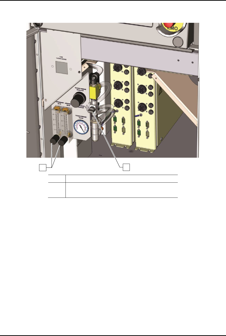
Item
Description
1 Flowmeter Adjustment Knobs
2
Impingement Air Valve
Figure 5-36 Adjusting the Impingement Heater Airflow (S2-9XXP Dual Conveyor)
1
2
S2-9XXX Series Dispensing System IOM Manual Calibration and Adjustment
5-34 © 2023 Nordson Corporation
5.17 Adjusting the Lift Table Speed
To adjust the lift table speed:
1. From the Fluidmove Main Menu, select
Configuration > Conveyor Setup > Test I/O.
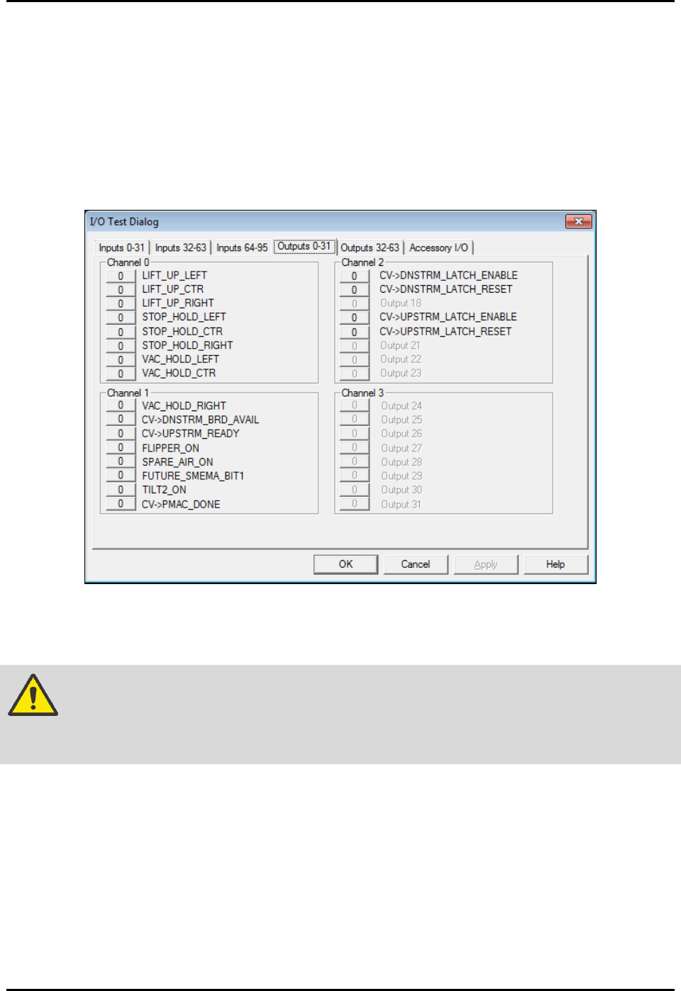
2. Select the tab labeled “Outputs 0-31” and locate the lift output buttons (Figure 5-41) for the
station to be adjusted (Lift_Up_Left, Lift_Up_Ctr, Lift_Up_Right).
3. Toggle the lift output buttons On (1) and Off (0) to lift and lower the table to test the speed
adjustment setting.
Figure 5-37 Conveyor I/O Test Dialog
4. If adjustment is necessary, open the dispensing area door.
WARNING! Do not reach into the dispensing chamber until yellow beacon light is displayed
and all system motion has stopped. If the heaters are hot, use extreme caution
when performing this operation.
5. Locate the Flow Control Valves (FCVs) for the appropriate lift table.
NOTE Flow control valve locations are shown in Figure 5-42 through Figure 5-44. If
the system has dispense heat only, the FCVs are located under the lift table. To
gain access to the FCVs, it may be necessary to move the dispensing head to
the rear of the machine.