Spectrum+Operating+Manual.pdf - 第192页
S2-9 XX X Se ri es Disp ensi n g Syst em IOM Man ual Parts Replacement 8-40 © 2023 Nordson Corporatio n 8.17.2 Replacing the 3-Way Valve Assembly To remove the 3-way valve assembly ( Figure 8- 30 ): 1. Perform a service …
S2-9XXX Series Dispensing System IOM Manual Parts Replacement
© 2023 Nordson Corporation 8-39
Item
Description
Item
Description
Not
Shown
Screws (2) 3 EMO Rear Bracket
1
EMO Contact Block Switch (Item 15)
4
EMO Actuator Switch (Item 15)
2 EMO Nut (included with Item 15)
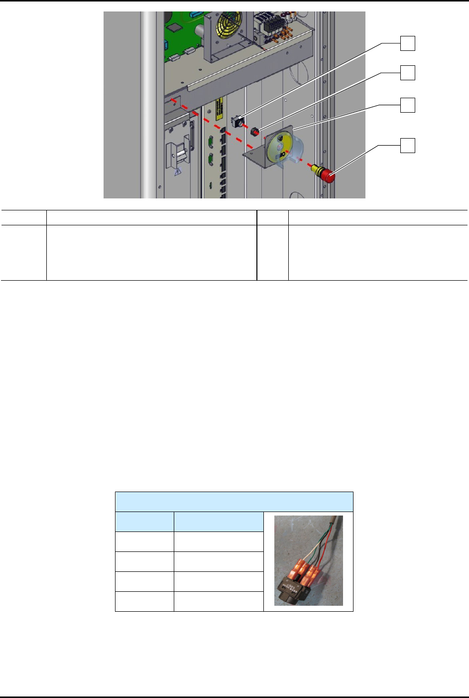
Figure 8-29 Replacing the Rear EMO Actuator Switch (Wiring Not Shown for Clarity)
To install the rear EMO actuator switch (Figure 8-29):
1. Install the EMO actuator switch through the front of the EMO rear bracket.
2. Apply plastic thread locker to the threads of the EMO nut.
3. Install a new EMO nut from the rear of the EMO rear bracket onto the EMO actuator
switch.
4. Tighten the EMO nut with the switch mounting tool.
5. Connect the EMO switch contact block switch to the EMO actuator switch.
6. Connect the power control cables to the EMO contact block switch, see Table 8-4.
Table 8-4 Power Control Cable Connections (EMO Switch)
EMO Switch
Contact # Color
11 Black
12 Red
21 White
22 Green
7. Install the EMO rear bracket to the dispensing system by tightening the two (2) screws.
8. Torque the two (2) screws to 5.6 Nm (50 in-lbs).
9. Close the rear door of the dispensing system.
3
2
1
4
S2-9XXX Series Dispensing System IOM Manual Parts Replacement
8-40 © 2023 Nordson Corporation
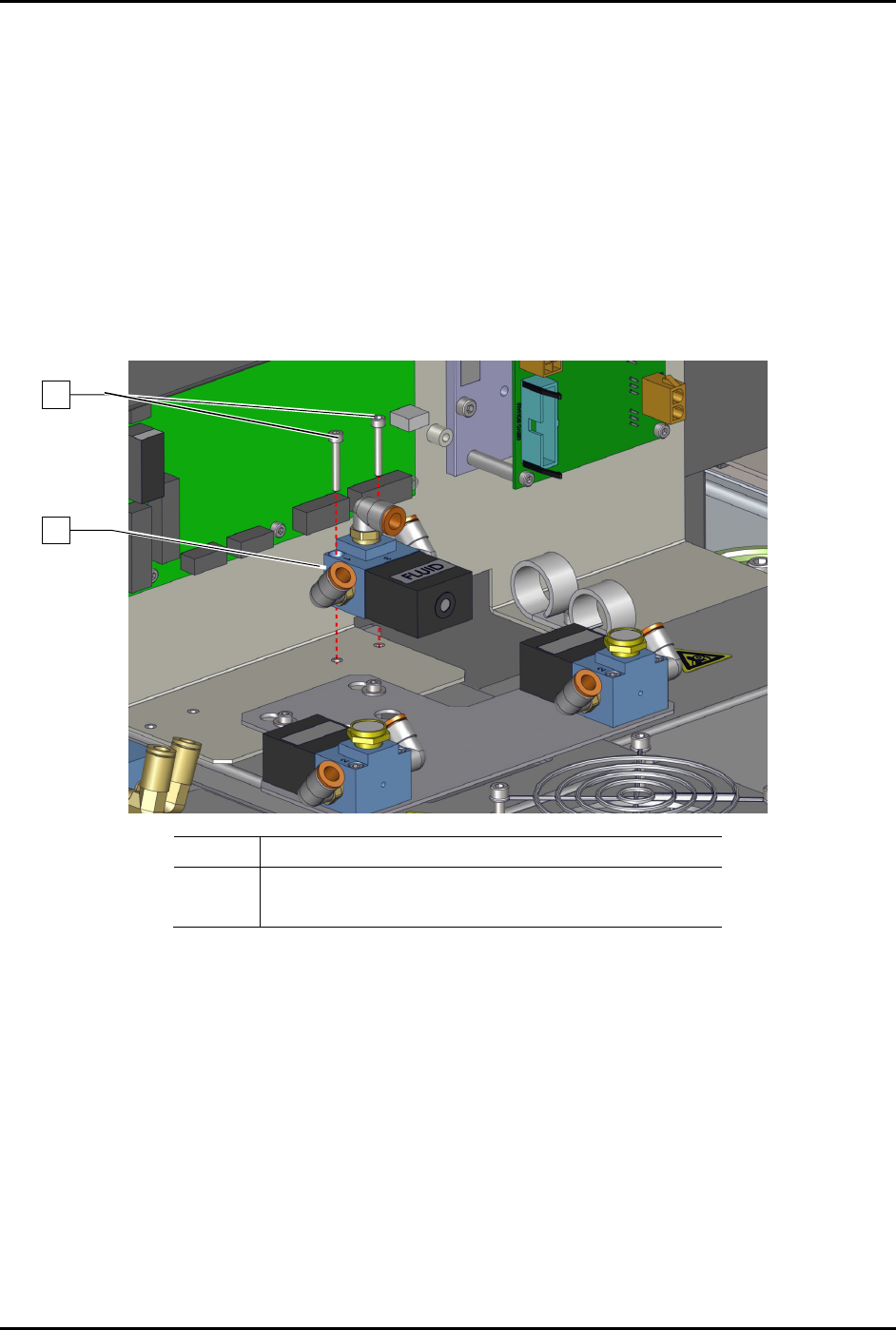
8.17.2 Replacing the 3-Way Valve Assembly
To remove the 3-way valve assembly (Figure 8-30):
1. Perform a service shutdown, see 2.14 Service Shutdown.
2. Open the rear door of the dispensing system.
3. Disconnect the pneumatic and electrical connections to the 3-way valve assembly.
Note the connection locations.
4. Remove the two (2) screws securing the 3-way valve assembly to the panel.
5. Remove the 3-way valve assembly.
Item Description
1 Screws (2)
2 3-Way, 24V Valve (Item 18)
Figure 8-30 Replacing the 3-Way Valve Assembly
To install the 3-way valve assembly (Figure 8-30):
1. Install the two (2) screws securing the 3-way valve assembly to the panel.
2. Torque the two (2) screws to 0.67 Nm (6 in-lbs).
3. Connect the pneumatic and electrical connections to the 3-way valve assembly.
4. Close the rear door of the dispensing system.
1
2
S2-9XXX Series Dispensing System IOM Manual Parts Replacement
© 2023 Nordson Corporation 8-41
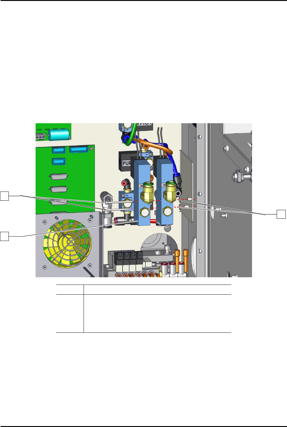
8.17.3 Replacing the 3-Way High Flow Valve
To remove the 3-way high flow valve (Figure 8-31):
1. Perform a service shutdown, see 2.14 Service Shutdown.
2. Open the rear door of the dispensing system.
3. Disconnect the pneumatic and electrical connections to the 3-way high flow valve.
Note the connection locations.
4. Remove the two (2) screws and two (2) washers securing the 3-way high flow valve to the
dispensing system.
5. Re
move the 3-way high flow valve from the dispensing system.
Item Description
1 Screws (2)
2 Washer
3 Valve, 3-Way, High Flow (Item 19)
4 Washer
Figure 8-31 Replacing the 3-Way High Flow Valve
To install the 3-way high flow valve (Figure 8-31):
1. Install the 3-way high flow valve with two (2) screws and two (2) washers to the dispensing
system.
2. Torque the two (2) screws to 1.4 Nm (12 in-lbs).
3. Connect the pneumatic and electrical connections to the 3-way high flow valve.
4. Close the rear door of the dispensing system.
1
1
2