Spectrum+Operating+Manual.pdf - 第49页
S2-9 XXX Se ri es Dispensing Sys te m IOM Man ual Safety © 2023 Nordson Co rporat ion 2-17 Situatio ns where LOTO pract ices might not be requ ired are when troubles hoot in g electrical, pneumat ic, or hydraulic compone…
S2-9XXX Series Dispensing System IOM Manual Safety
2-16 © 2023 Nordson Corporation
2.13 Interlock
The interlock is an electronic connection that immediately cuts the power to any motion and pneumatic
actuators. If the dispensing area door is opened during dispensing, the interlock is activated and all
dispensing activity immediately stops to protect the operator from injury.
2.13.1 Interlock Recovery
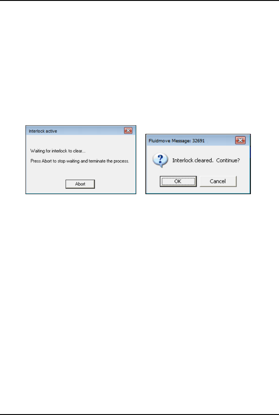
When the interlock is triggered, Fluidmove will display an Interlock Active message (Figure 2-11).
To recover from a shutdown triggered by the interlock:
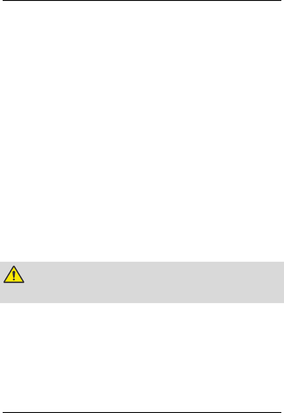
1. Close the dispensing area door.
2. When the Fluidmove Message 32691 appears, click
OK to continue dispensing or Cancel to
abort (Figure 2-12).
Figure 2-11 Interlock Active Message
Figure 2-12 Interlock Cleared Message
2.14 Service Shutdown
Before performing any service or parts replacement, the dispensing system should be shutdown
as follows:
1. Shutdown the dispensing system, see 4.8.2 System Shutdown.
2. Perform a “Lockout/Tagout of Electrical and Pneumatic Energy” as described below.
2.15 Lockout/Tagout of Electrical and Pneumatic Energy
Companies may differ in their Lockout/Tagout (LOTO) procedures and requirements, and it is the
responsibility of the end user to determine compliance with local safety procedures. The purpose of any
LOTO effort is to help avoid injury or dispensing system damage due to unexpected energizing of
equipment, start up, or the release of stored energy during repair, maintenance, and operation of
equipment. Situations where LOTO practices may be employed on the dispensing system include:
• Adjusting cables, belts, pulleys, or moving parts
• Servicing bearings or motors
• Troubleshooting, servicing, or replacing electronic components or assemblies
• Troubleshooting, servicing, or replacing pneumatic components or assemblies
S2-9XXX Series Dispensing System IOM Manual Safety
© 2023 Nordson Corporation 2-17
Situations where LOTO practices might not be required are when troubleshooting electrical, pneumatic,
or hydraulic components or assemblies that make de-energizing the whole system impractical.
Troubleshooting or servicing the dispensing system while powered up and operating should only be
accomplished by fully trained and qualified personnel. There should always be a second person present
when performing maintenance on a system under power.
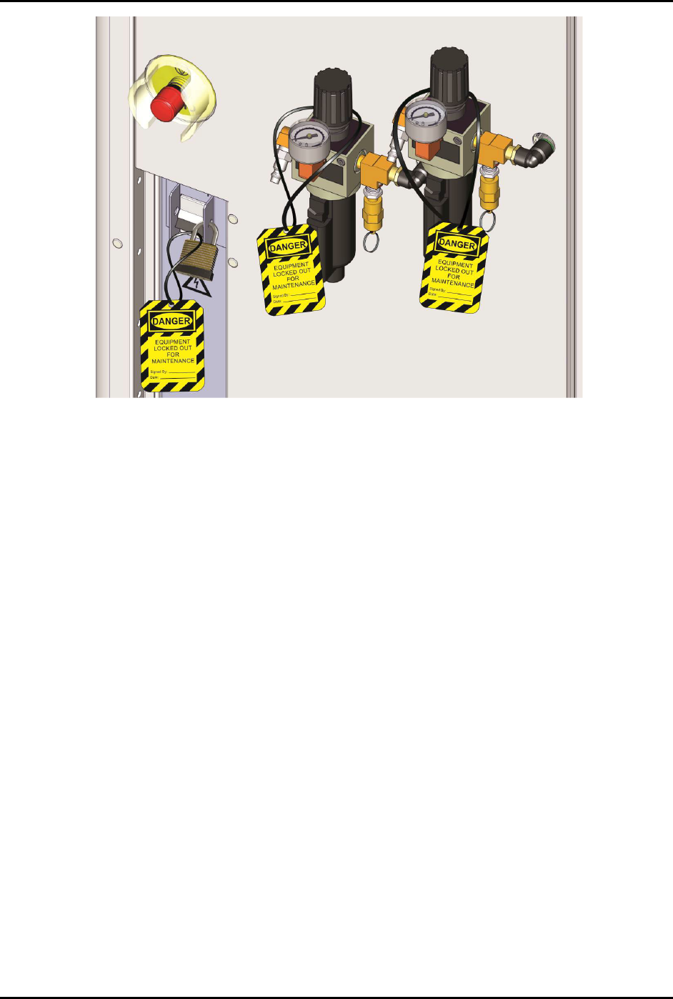
To lockout/tagout the electrical and pneumatic energy (Figure 2-13):
1. Turn the main circuit breaker on the rear of the system to the
OFF (0) position.
2. Unplug the main power cable from the back of the power manager.
3. Rotate the main air pressure knob counterclockwise until the gauge registers 0 kPa (0 psi)
and then disconnect the main air supply by the quick release fitting.
4. Install an approved, keyed lock on the locking flange of the main circuit breaker so it cannot
be turned on; tag it with an approved tag.
Ensure that the owner, date, reason, and estimated time for repair are clearly marked on
the tag.
5. Install an approved lockout clamp and keyed lock onto the power connector so it cannot be
reconnected to the power manager and attach an approved tag.
Ensure the owner, date, reason, and estimated time to repair are clearly marked on
the tag.
6. Install an approved lockout clamp and keyed lock onto the pneumatic fitting so it cannot be
reconnected to the main air regulator and attach an approved tag.
Ensure the owner, date, reason, and estimated time to repair are clearly marked on the
tag.
NOTE Warning tags document the name of the technician taking the equipment out of operation,
the date, and other facility-required information. It is a warning that the equipment cannot
be put back into operation until the authorized technician has removed the tag.
WARNING! If your dispensing system is equipped with a heater, allow sufficient time for the
heater to cool prior to performing maintenance or service. Failure to do so may
result in serious burn injury.
S2-9XXX Series Dispensing System IOM Manual Safety
2-18 © 2023 Nordson Corporation
Figure 2-13 Electrical/Pneumatical Lockout/Tagout