Printer 710_810 v8 Sensors.pdf - 第12页
SENS ORS SAFETY SWIT CH 31.12 Technical Reference Manual Chapter Iss ue 2 Oct 06 T esting/ Adjustment T o adjust the safety swit ch, physicall y move the body of the switch to ensure that 6mm of cover movement activat es…
SENSORS
SAFETY SWITCH
Chapter Issue 2 Oct 06 Technical Reference Manual 31.11
SAFETY SWITCH
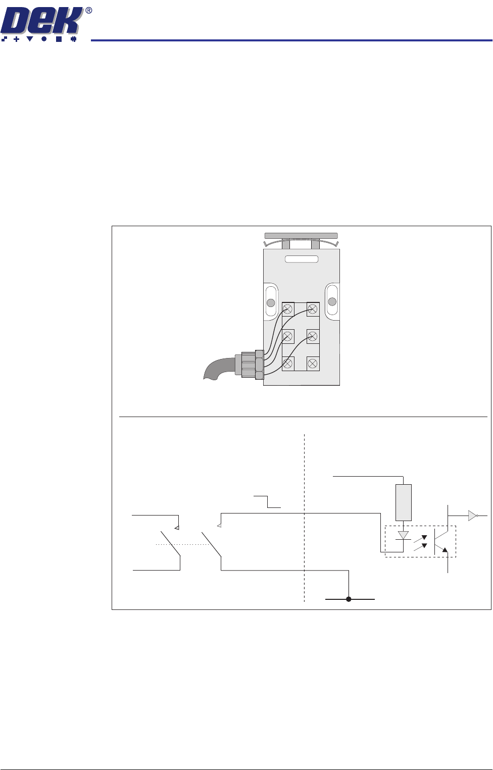
Description The safety switch is a device fitted to the printhead cover designed to provide
operator safety.
The design of the internal anti-tamper cams also act as a latch. A 6mm
movement of the switch activator 'open circuits' the safety contacts. There are
3 sets of contacts in the switch but only 2 of the sets, both normally open (NO),
are used by the machine. One set of contacts is used as a digital input to inform
the PC that a cover has been opened, the other set is used as part of the system
safety loop to cut the system power.
The cover interlock signal is pulled low when the front cover is opened.
Figure 31-12 Safety Switch Schematic
Safety Switch
Digital Input
V+ (User)
Opto-isolator
1K8
0V (User)
12V
0V
21
13
14
22
Part of
System
Safety
Loop
1314
21
33
34
22

SENSORS
SAFETY SWITCH
31.12 Technical Reference Manual Chapter Issue 2 Oct 06
Testing/
Adjustment
To adjust the safety switch, physically move the body of the switch to ensure
that 6mm of cover movement activates the switch.
Figure 31-13 Voltage Diagram
Cover Closed Open Closed
12V
0V
Closed
Circuit
Closed
Circuit
Open
Circuit
Continuity
Signal
SENSORS
MICROSWITCH SENSOR
Chapter Issue 2 Oct 06 Technical Reference Manual 31.13
MICROSWITCH SENSOR
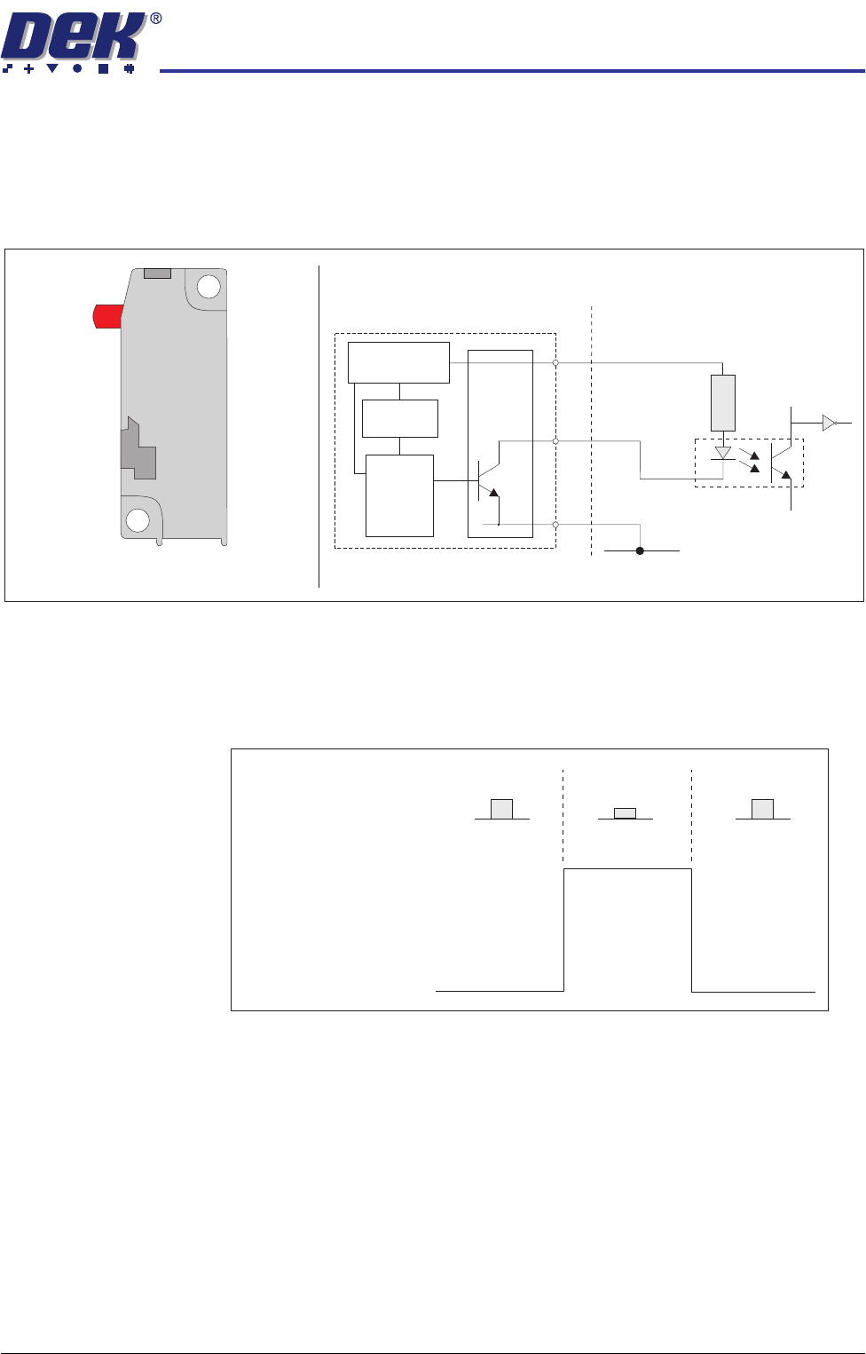
Description The microswitch sensor used is a solid state microswitch with no mechanical
contacts. The plunger operates a Hall effect sensor triggering the transistorized
output.
Figure 31-14 Microswitch Sensor and Schematic
Testing/
Adjustment
Testing can be carried out with the microswitch in circuit by measuring the
voltage between pin 2 (signal) and pin 3 (0V), Voltage Diagram figure below,
refers.
Figure 31-15 Voltage Diagram
Digital Input
V+ (User)
Opto-isolator
1K8
0V
Squeegee/ProFlow Home Microswitch
o
+
-
s
Voltage
Regulator
Trigger
Circuit
and
Amplifier
Hall Effect
Sensor
Block Diagram of Microswitch
1
2
3
Switch Position
Released Depressed Released
12V
0V
Voltage
Output at
Pin 2 (signal)