Printer 710_810 v8 Sensors.pdf - 第13页
SENSOR S MICROSW ITCH SE NSOR Chapter Issue 2 Oct 06 Technical Reference Manual 31.13 MICROSWITCH SENSOR Descriptio n The microswit ch sensor used is a solid st ate micr oswitch with n o mechanical conta ct s. The plunge…

SENSORS
SAFETY SWITCH
31.12 Technical Reference Manual Chapter Issue 2 Oct 06
Testing/
Adjustment
To adjust the safety switch, physically move the body of the switch to ensure
that 6mm of cover movement activates the switch.
Figure 31-13 Voltage Diagram
Cover Closed Open Closed
12V
0V
Closed
Circuit
Closed
Circuit
Open
Circuit
Continuity
Signal
SENSORS
MICROSWITCH SENSOR
Chapter Issue 2 Oct 06 Technical Reference Manual 31.13
MICROSWITCH SENSOR
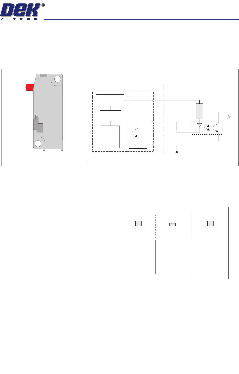
Description The microswitch sensor used is a solid state microswitch with no mechanical
contacts. The plunger operates a Hall effect sensor triggering the transistorized
output.
Figure 31-14 Microswitch Sensor and Schematic
Testing/
Adjustment
Testing can be carried out with the microswitch in circuit by measuring the
voltage between pin 2 (signal) and pin 3 (0V), Voltage Diagram figure below,
refers.
Figure 31-15 Voltage Diagram
Digital Input
V+ (User)
Opto-isolator
1K8
0V
Squeegee/ProFlow Home Microswitch
o
+
-
s
Voltage
Regulator
Trigger
Circuit
and
Amplifier
Hall Effect
Sensor
Block Diagram of Microswitch
1
2
3
Switch Position
Released Depressed Released
12V
0V
Voltage
Output at
Pin 2 (signal)
SENSORS
PRESSURE SENSOR
31.14 Technical Reference Manual Chapter Issue 2 Oct 06
PRESSURE SENSOR
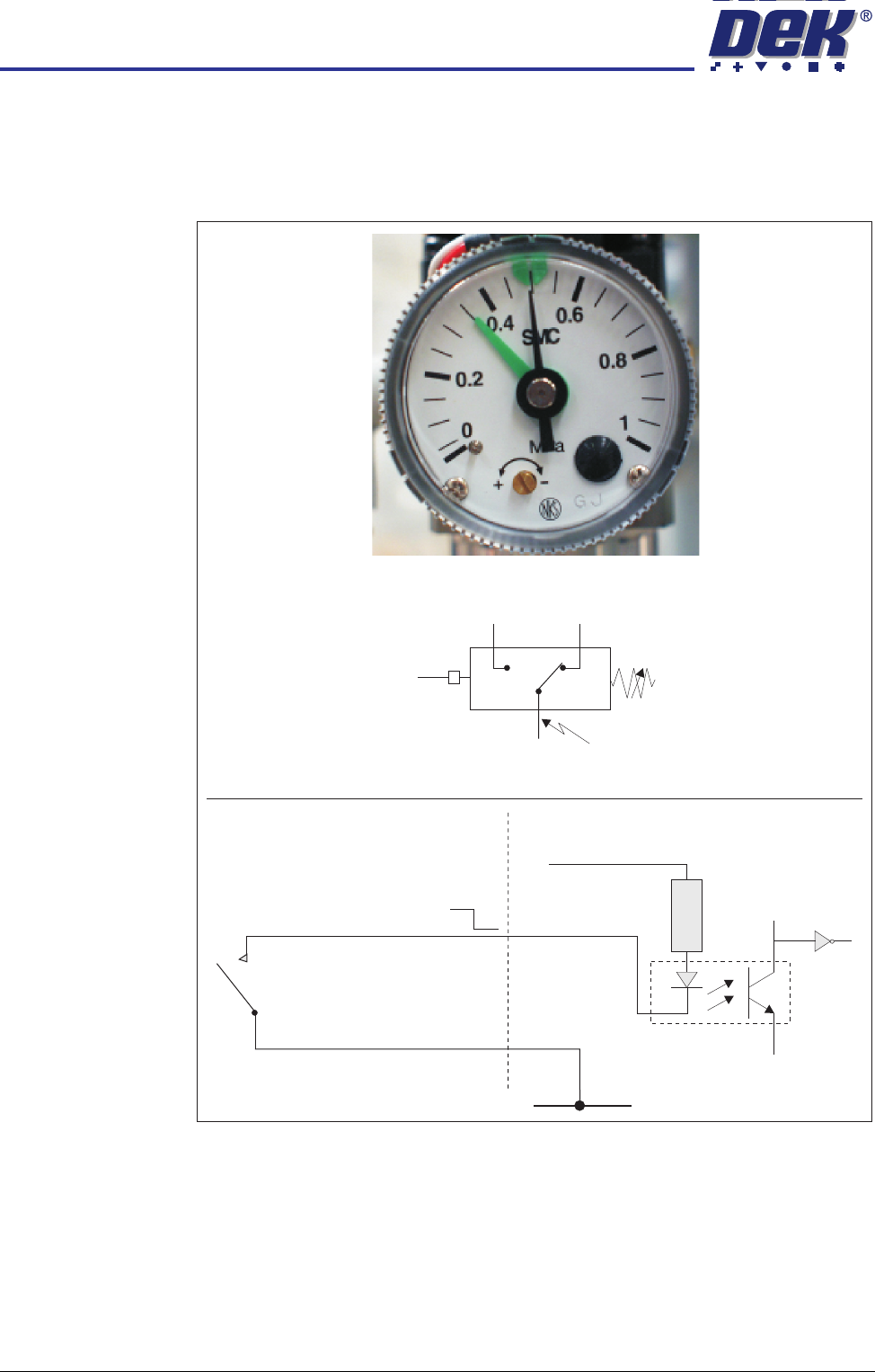
Description The pressure sensor switch is wired as a normally open (NO) switch which is
closed by the air pressure exceeding the set point.
Figure 31-16 Pressure Sensor Schematic
Digital Input
V+ (User)
Opto-isolator
1K8
0V (User)
12V
0V
Pressure Sensor Symbol
Pressure Sensor and Gauge
P
Common
NC
NO