Printer 710_810 v8 Sensors.pdf - 第17页
SENSOR S STRAI N GAU GE SE NSOR Chapter Issue 2 Oct 06 Technical Reference Manual 31.17 STRAIN GAUGE SENSO R Descriptio n The sensors ar e produced in a full resist ive Wheat stone bri dge configur ation that is temperat…
SENSORS
GIANT MAGNETO RESISTIVE SENSOR (GMR)
31.16 Technical Reference Manual Chapter Issue 2 Oct 06
GIANT MAGNETO RESISTIVE SENSOR (GMR)
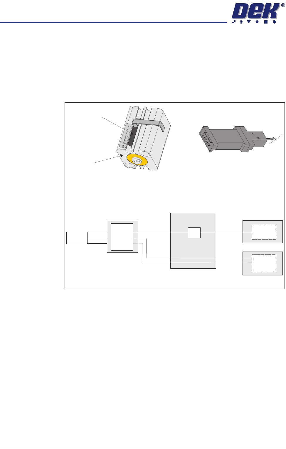
Description The sensor reacts to the magnetic field produced by the magnetic end of the
cylinder piston. This produces an analogue signal proportional to the piston
position, ie the closer the piston to the sensor the larger the analogue signal.
This analogue signal is fed to the Analogue to Digital Converter (ADC) on the
print carriage I/O Node 3 PCB and the digital output is fed via the CAN bus to
the NextMove ES card.
Figure 31-18 Giant Magneto Resistive Schematic
Testing/
Adjustment
The sensor does not require adjustment. In use the assembly is calibrated -
see the ProFlow Module Chapter for details.
+12V
Print Carriage
I/O Node 3
0V
Sig
0V
+12V
M36 Machine Control
M37 Power Supply Crate
NextMove
ES Card
Paste
Level
Amplifier
GMR
Sensor
Paste Level Amplifier
Pneumatic Actuator and GMR Sensor
Pneumatic
Actuator
GMR Sensor
15
0
30
Output 0.5V - 5V
Digital
Out
Analog
In
ADC
CAN Bus
Power
Distribution
PCB
SENSORS
STRAIN GAUGE SENSOR
Chapter Issue 2 Oct 06 Technical Reference Manual 31.17
STRAIN GAUGE SENSOR
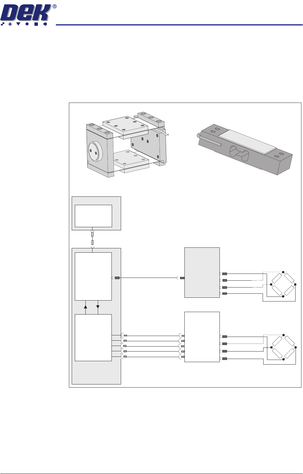
Description The sensors are produced in a full resistive Wheatstone bridge configuration
that is temperature and creep compensated. It uses a thin foil as one of the
resistive elements of the bridge. If a force is applied (weight) such that the
measuring foil is stretched, the lengthening of the foil causes its resistance to
vary. This change in resistance is detected and passed to a high gain DC
amplifier.
Testing/
Adjustment
The sensors do not require adjustment. In use the assemblies are calibrated -
see the Squeegee chapter or the relevant underscreen cleaner chapter for
details.
Solvent Level Strain Gauge
Squeegee Strain Gauge
M36
Machine Control
Enclosure
USB
PC
Single Board
Computer
(SBC)
NextMove ES
(I/O Node 1)
I/Ps
O/Ps
NextMove
Interface
AN IN0 -
AN IN0 +
Solvent
Load Cell
Solvent
Level
Amp
-V
+V
-IN
+IN
0V USR
+12V
-12V
Print
Carriage
I/O Node 3
CAN Bus
CAN
In
0V
+V
-IN
+IN
Squeegee
Pressure
Load Cell

SENSORS
TEMPERATURE AND HUMIDITY SENSOR
31.18 Technical Reference Manual Chapter Issue 2 Oct 06
TEMPERATURE AND HUMIDITY SENSOR
The temperature and humidity sensor is an integral part of the print carriage I/
O Node 3 PCB and as such there is no adjustment and setting available for this
sensor.