SOM-1861-001.pdf - 第8页
5 AJYESO-P 3. Appearance of Machine 3. Appearance of Machine 0505-001 A Component Dispersion Prevention Plate Vie w A Stopper Knob Detachable Plate Guide Plate Locate Pin Hole Front Side of Machine Attach Detach

4 AJYESO-P0505-001
1. Scope
1. Scope
To prevent minute components from dispersing on the PCB beforehand, the
area preventing the dispersion can be expanded by covering the area except
for the minimum (smallest) one with a detachable plate.
2. Specifications
Item Description Special Remarks
1. Applicable Models • TCM-X110, TCM-X110M
• TCM-X210
• TCM-X300, TCM-X300S
2. Required Plates Use PLATE-1 or PLATE-2 properly according to the
size of the components to be mounted.
• PLATE-1
Opening : φ 26 mm
Mounting Component Size :
0.6 mm × 0.3 mm to 5 mm × 5 mm
• PLATE-2
Opening : 50 mm x 60 mm
Mounting Component Size :
0.6 mm × 6.3 mm to 15 mm × 15 mm
• Common Items for PLATE-1 and PLATE-2
Height of Component : Max. 4.5 mm
Height of Previously-Placed Component :
Max. 4.5 mm
(Upward Warpage of PCB : Max. 1 mm)
Offset for Nozzle Attachment : Max. 0.8 mm
The above-described mounting component size represents
the range where the outline of a component does not
interfere with the opening and more than 0.9 mm can be
secured as a leeway between the lower face of the
normally picked component and the upper face around
the opening
Note : When PLATE-1 is used for the mounting
components taller than 2.5 mm, a component will
be flipped vertically if not picked up correctly,
causing the bottom of the component to interfere
with the upper face around the opening of
PLATE-1.
5 AJYESO-P
3. Appearance of Machine
3. Appearance of Machine
0505-001
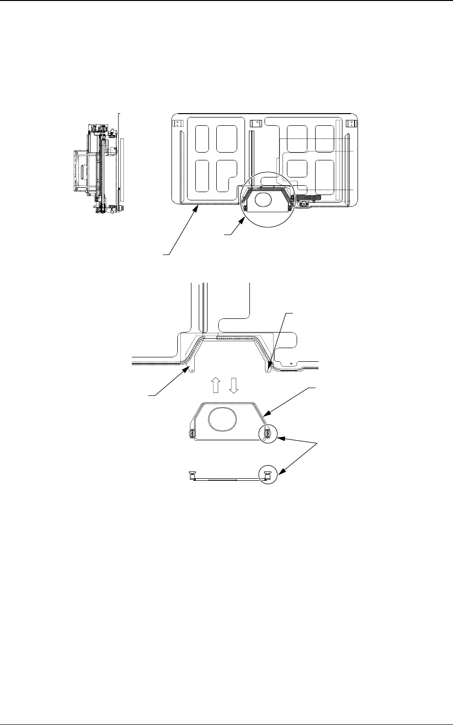
A
Component Dispersion
Prevention Plate
View A
Stopper Knob
Detachable Plate
Guide Plate
Locate Pin Hole
Front Side of Machine
Attach Detach
6 AJYESO-P
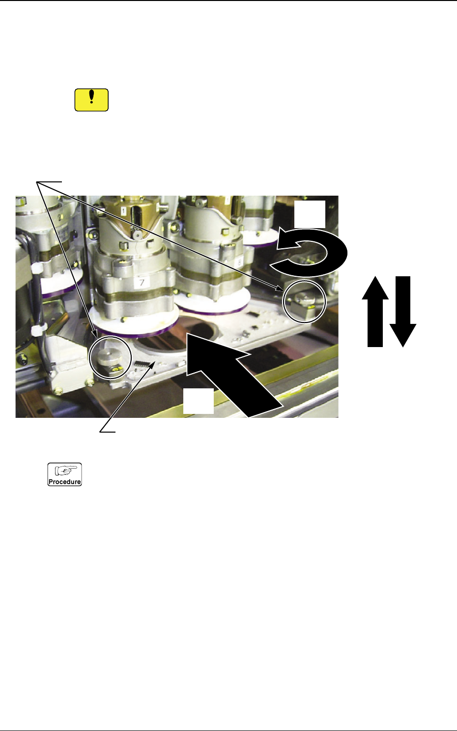
4. Attachment and Detachment of Detachable Plate
Follow the steps below to attach or detach the detachable plate.
While detaching the detachable plate, be sure not to let it interfere
with a nozzle.
4.1 Attachment of Detachable Plate
(1) Pull up the stopper knobs, rotate them by 90° then lock them at
their upper limits.
(2) Insert the detachable plate horizontally along the side face of the
guide plate (internal side).
(3) Rotate the stopper knobs by 90° and release the lock.
(4) Lower the stopper knobs to their lower limits. At this time, confirm
that the stopper knobs are inserted completely into the locate pin
holes.
0505-001
4. Attachment and Detachment of Detachable Plate
(1)
(4)
(2)
(3)
Detachable Plate
Detachable Plate Stopper Knobs (2 pcs.)
Notice