TK29609.Auto Scale Correction.pdf - 第7页
SMT Software Engineering Group IM Operations Y AMAHA MOTOR CO., L TD MDOC-SOFT50390 7/8 4.4. Log saving Scale corre ction value of each view and gap of the imaging area height a re output t o the inspection resu…
SMT Software Engineering Group
IM Operations YAMAHA MOTOR CO., LTD
MDOC-SOFT50390
6/8
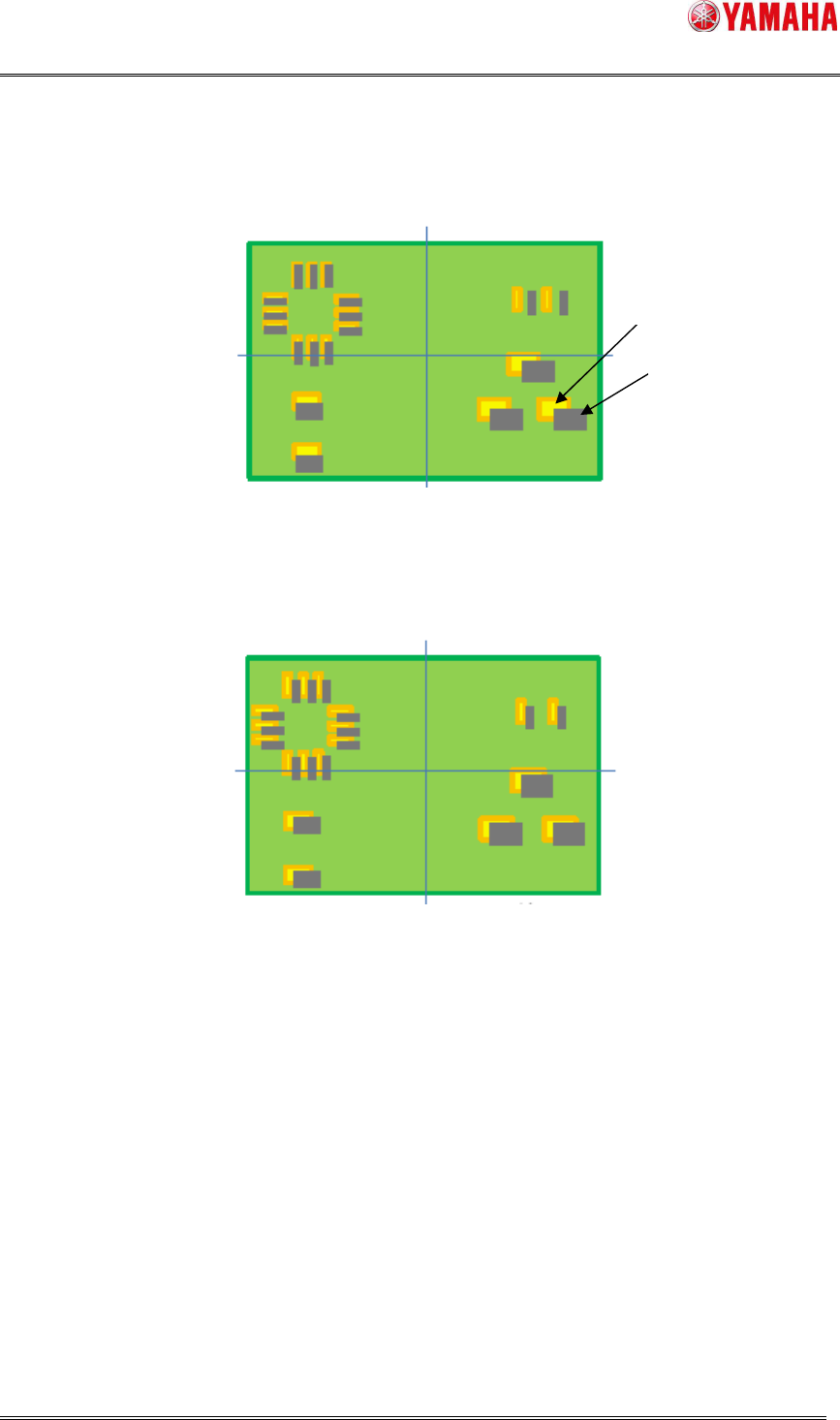
4.2. How to acquire auto scale correction value
(1) First, each solder position is measured without scale correction.
Fig 4.2 1
st
measurement (without corrected)
(2) Scale correction value is calculated based on gap of the solder positions.
(3) Solder positions are measured again considering the correction value.
Fig 4.3 2
nd
measurement (with corrected)
4.3. Utility
4.2.1. [View Test] button
Auto scale correction works when [View Test] is executed on the [Inspection] – [View] –
[Adjust] screen.
4.2.2. [Object Test] button
Auto scale correction works when [Object Test] is executed on the [Inspection] – [Object]
– [Adjust] screen.
Solder
Pattern
SMT Software Engineering Group
IM Operations YAMAHA MOTOR CO., LTD
MDOC-SOFT50390
7/8
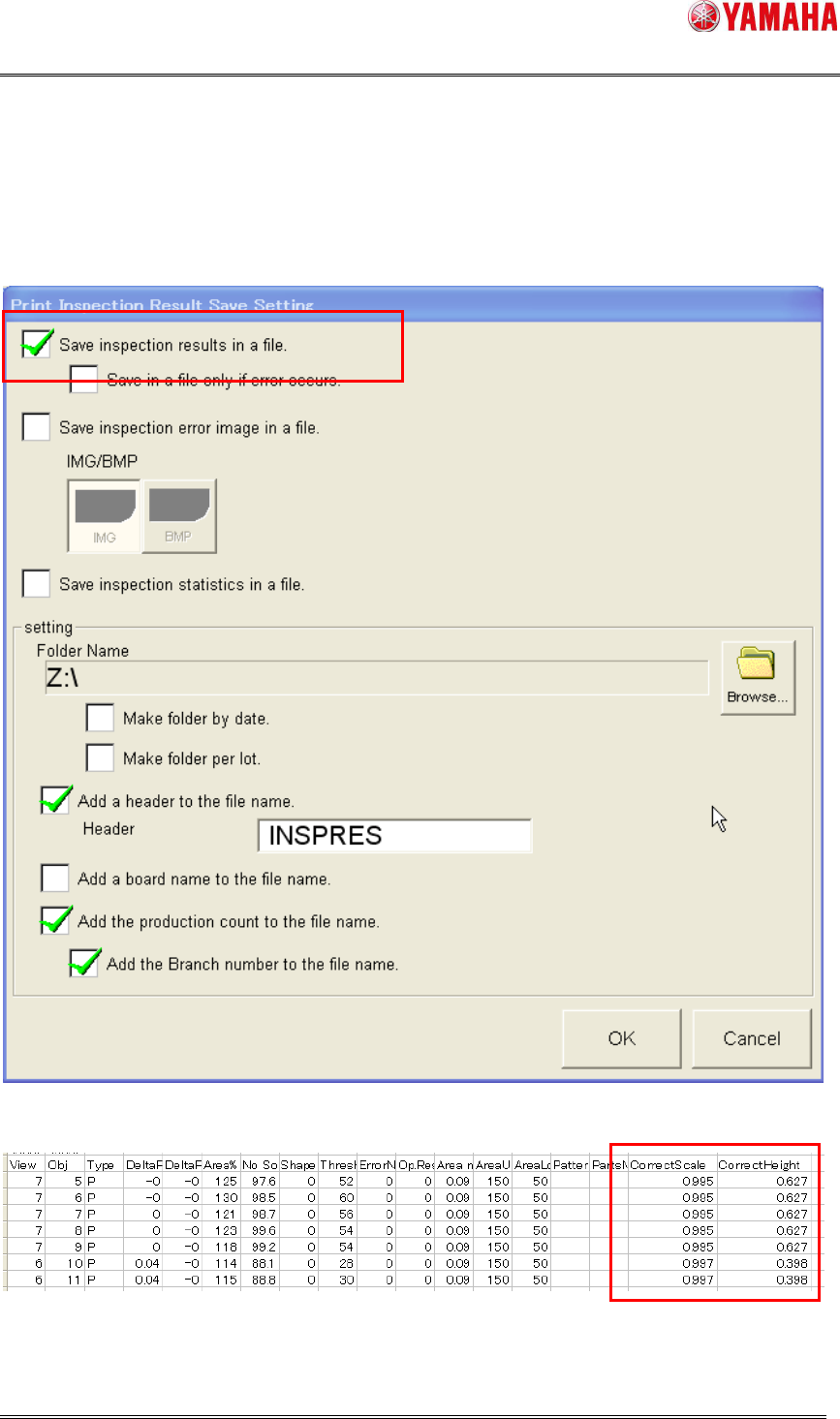
4.4. Log saving
Scale correction value of each view and gap of the imaging area height are output to the
inspection result file.
Fig 4.4 [Software Setting] – [Model] – [Print Inspection]
Fig 4.5 Inspection result file
SMT Software Engineering Group
IM Operations YAMAHA MOTOR CO., LTD
MDOC-SOFT50390
8/8
5. Limitation
On a printer without this function supported, the board data settings of [Auto Scale
Correction] are not saved. Please update the software to a version with Auto Scale
Function supported.
While this function is used, calculation of correction value is performed twice for each
view. Therefore, inspection time may be longer if there are many inspection objects in a
view.
This function can correct the scale up to ± 1 mm. If a board is warping more than 1mm,
adjacent solder may be wrongly inspected and correction value is not acquired properly.