TK26522.Chip Vacuum Check.pdf - 第5页
S M T S o f t w a r e E n g i n e e r i n g G r o u p I M O p e r a t i o n s Y A M A H A M O T O R C O . , L T D MDOC-SOFT50395 2.3 Timing to output errors Between “after camera recognition of picked parts” and “before …
SMT Software Engineering Group
IM Operations YAMAHA MOTOR CO., LTD
MDOC-SOFT50395
2. Function overview
2.1 Outline
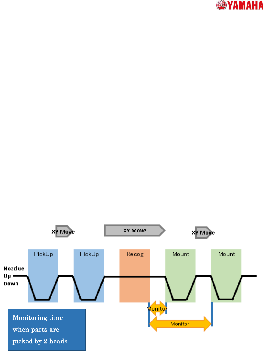
Between “after camera recognition of picked parts” and “before mounting”, vacuum level is
monitored for checking of parts existence. It memorizes the highest vacuum level, and
judges “parts fall” if the vacuum level drops below a certain level(※) from the peak.
(※) Specified for each nozzle type in Machine Setting.
2.2 Period of Chip Vacuum Check
Vacuum level is monitored between “after camera recognition of picked parts” and “before
mounting” for all heads(nozzle type) that are set with [Chip Vacuum Check] active and also
picking parts.
Fig 2.1 Vacuum level monitoring time

SMT Software Engineering Group
IM Operations YAMAHA MOTOR CO., LTD
MDOC-SOFT50395
2.3 Timing to output errors
Between “after camera recognition of picked parts” and “before mounting”, it monitors
vacuum level for checking of parts existence. The error is not output just after a chip is
dropped off. Timing to display the error is as follows.
When chip is dropped from mounting head
The error message is displayed when XY-axis arrives at the mounting position. At
this time, the error message is displayed for each error head.
When chip is dripped from other than mounting head
The error occurs when mounting of mount head is completed. At this time, the error
message is displayed for each error head.
SMT Software Engineering Group
IM Operations YAMAHA MOTOR CO., LTD
MDOC-SOFT50395
3. Error Message
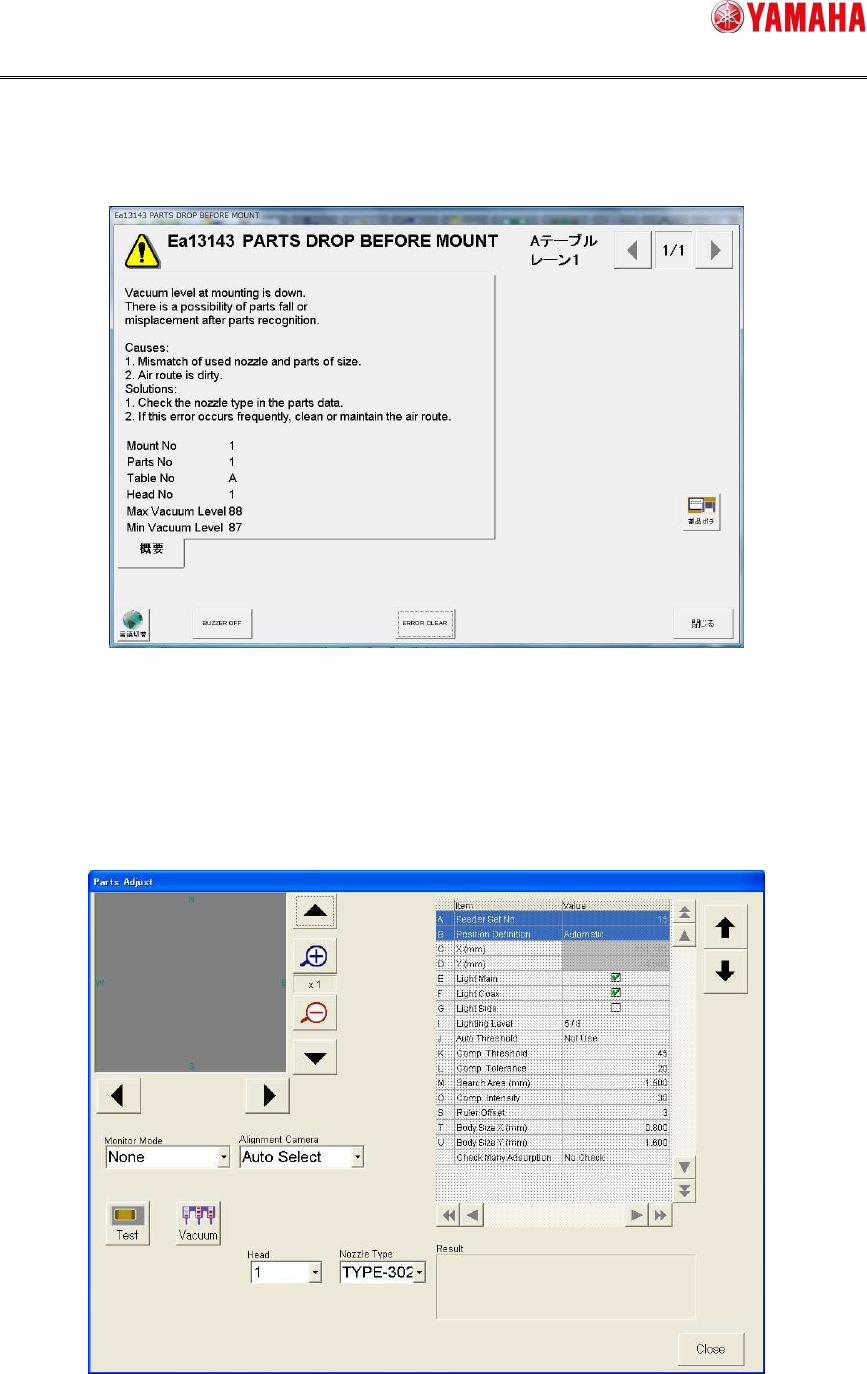
When parts fall is detected, the following error message is displayed.
Fig 3.1 Error message dialog
When parts fall is detected, the error message is displayed for each head.
By clicking the [Parts Adj] button on the message, you can see the picking condition and
vacuum level of the error head.
Fig 3.2 Parts Adjust screen