Maintenance Schedule保养计划.pdf - 第36页
Vision XP+ V AC / XP+ / XP / XS Page 45 2 Mainte nance 2.12 Gas t ake-of f point: N 2 regulation Service Instructions V ersion 1.3 2.12 Ga s take-off poi nt: N2 regulation Fig. 2-71 Gas take-o ff point Fig. 2-72 Cleaning…
Page 44 Vision XP+ VAC / XP+ / XP / XS
2 Maintenance
2.11 Pyrolysis
Service Instructions
Version 1.3
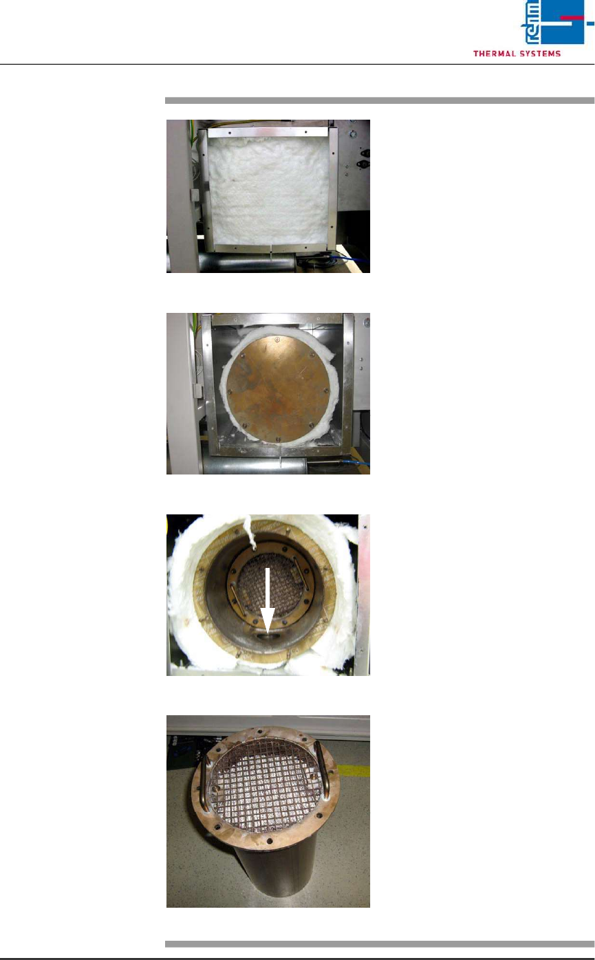
Fig. 2-67 Removing the Insulation
Fig. 2-68 Loosening the Nuts
Fig. 2-69 Removing the Insulation
Fig. 2-70 Lifting off the Grate
3. Remove the white insulation
which now becomes visible (see
Fig. 2-67). The cover of the
pyrolysis unit becomes visible
as well.
4. Loosen the nuts on the
granulate container (see
Fig. 2-68) and lift it out along
with the granulate (see
Fig. 2-69). It must be assured
that the nuts and the washers
do not fall into the pipe
connection.
5. Remove the screws which
secure the grate and lift the
grate and Gauze Filter off (see
Fig. 2-70).
6. Inspect the granulate for
contamination by breaking open
several pellets. If the granulate
is dark colored all the way
through, it has become
saturated and must be
replaced.
7. Fill the container with new
granulate under dust-free
conditions.
8. Apply copper paste to the
threads. Copper paste is heat-
resistant up to 1000° C.
If the old nuts need are no
longer usable, do not replace
them with stainless steel or zinc
plated nuts.
9. Reinstall the granulate
container by following the above
instructions in reverse order,
insert the insulation and the
seals (or replace if damaged)
and secure the cover with the
screws.
Vision XP+ VAC / XP+ / XP / XS Page 45
2 Maintenance
2.12 Gas take-off point: N2 regulation
Service Instructions
Version 1.3
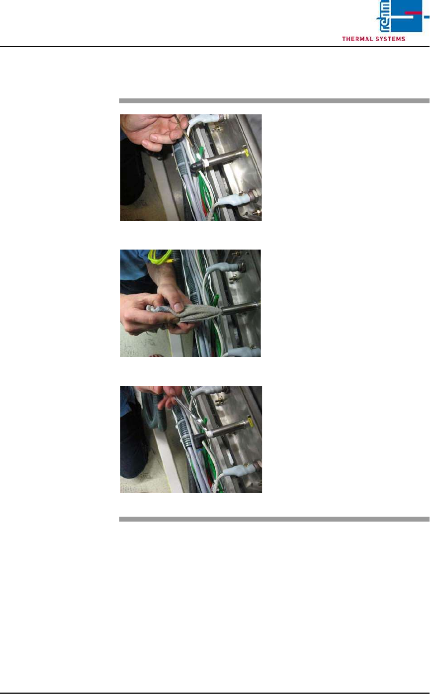
2.12 Gas take-off point: N2 regulation
Fig. 2-71 Gas take-off point
Fig. 2-72 Cleaning the gas take-off point
Fig. 2-73 Sealing the gas take-off point
The gas take-off point for N2
regulation is located in the peak 2
bottom.
Consumable materials, tools:
• Wrench
• 8 mm metal rod
• Teflon tape
• Rag
Procedure:
1. Remove the fitting from the
take-off point.
2. Lay the rag over the metal rod
and use it to clean the take-off
point.
3. In order to reseal the gas take-
off point after cleaning, wrap the
thread with Teflon tape and
tighten the fitting with a wrench.
Page 46 Vision XP+ VAC / XP+ / XP / XS
2 Maintenance
2.13 Residual Oxygen Meter
Service Instructions
Version 1.3
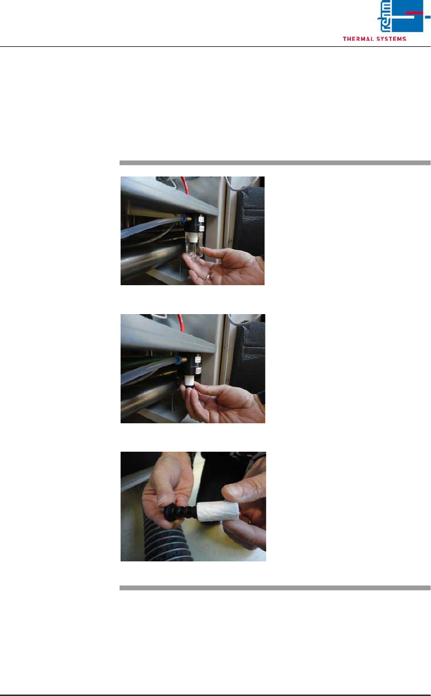
2.13 Residual Oxygen Meter
The residual oxygen meter are located at the back of the system.
2.13.1 Replacing the Pre-Filter
Fig. 2-74 Unscrew the filter casing
Fig. 2-75 Unscrew the filter insert
Fig. 2-76 Put on the fluorocarbon filter
As well as the activated carbon is
replaced, the fluorocarbon filter has
also to be exchanged.
Procedure:
Unscrew the filter casing and the flu-
orocarbon filter insert.
Put the new fluorocarbon filter insert
onto the element holder and mount
together in reversed order.