00197962-01_2nd_HMI_and_Tower_Light_en.pdf - 第26页
Installing a Second Human Machine Interface Installing the HMI Tower Kit 2.4.5 Step 5: Connecting the HMI Frame Cables to the Base Machine 26 Assembly Instructions SIPLACE E 2.4.5 2 . 4 . 5 S t e p 5 : C o n n e c t in g…
Installing a Second Human Machine Interface
2.4.4 Step 4: Connecting the Cables to the Monitor Installing the HMI Tower Kit
Assembly Instructions SIPLACE E 25
2.4.4
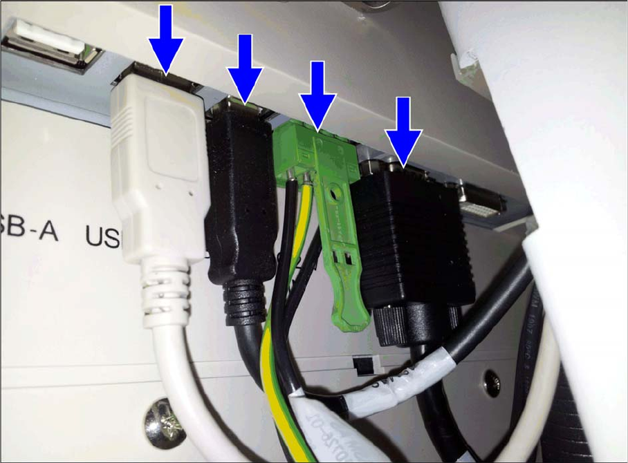
2.4.4 Step 4: Connecting the Cables to the Monitor
Step 4: Connecting the Cables to the Monitor
► Connect the HMI frame top cables to the monitor.
Installing a Second Human Machine Interface
Installing the HMI Tower Kit 2.4.5 Step 5: Connecting the HMI Frame Cables to the Base Machine
26 Assembly Instructions SIPLACE E
2.4.5
2.4.5 Step 5: Connecting the HMI Frame Cables to the Base Machine
Step 5: Connecting the HMI Frame Cables to the Base Machine
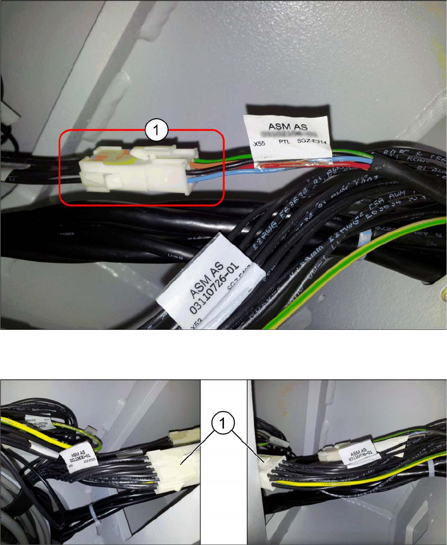
► Connect the HMI frame tower light cable [03115364-xx] to –X55 of the HMI LOC cable.
Location 1: Cable, HMI LOC1 (two safety loops) [03110630-xx]
Location 2: Cable, HMI LOC2 (two safety loops) [03110636-xx]
► Connect the HMI frame pushbuttons emergency switch cable [03110726-xx] (1) to –X53 of the HMI
LOC cable:
Location 1: Cable, HMI LOC1 (two safety loops) [03110630-xx]
Location 2: Cable, HMI LOC2 (two safety loops) [03110636-xx]
Installing a Second Human Machine Interface
2.4.5 Step 5: Connecting the HMI Frame Cables to the Base Machine Functional Verification After Installation
Assembly Instructions SIPLACE E 27
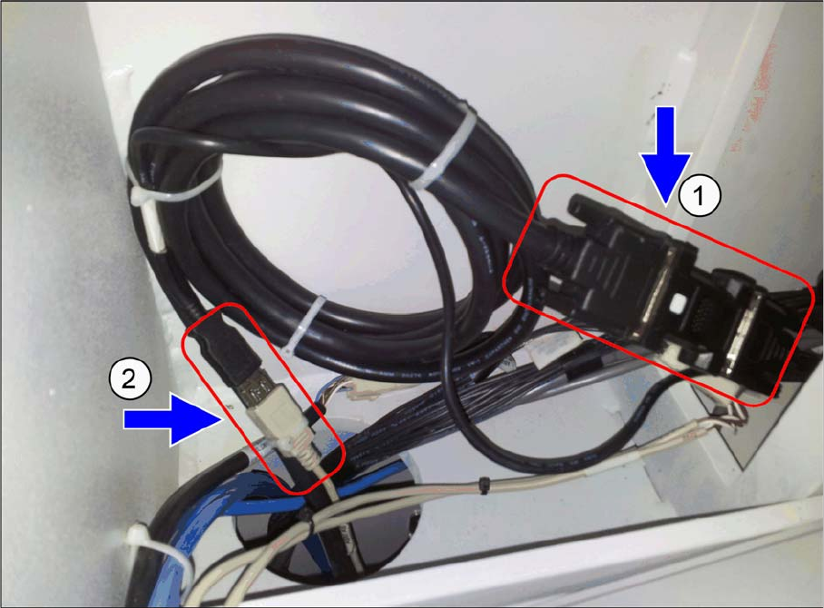
► Connect the HMI frame DVI-VGA cable male [03102206-xx] (1) to the DVI female adapter of exten
-
sion cable [03102207-xx].
► Connect the HMI frame USB A plug [03102208-xx] (2) to the USB A receptacle of the extension cable
[03102211-xx].
2.5
2.5 Functional Verification After Installation
Functional Verification After Installation
The touch screen monitor and the keyboard should be functional after machine boots up.