X-Series-Maintenance-Manual(1).pdf - 第13页
Introduction Minor and Major Maintenance Maintenance Notes Maintenance Manual SIPLACE X Series 13 Maintenance Notes 1.3 Maintenance Notes See also 1.1.7 Saf ety Instructio ns f or Maintenance Tasks [ ➙ 10] Minor an d M…
Introduction
Preparatory Work... Safety Instructions for Maintenance Tasks
12 Maintenance Manual SIPLACE X Series
► Alternative: Attaching warning signs
If a machine can be locked, it must be. However, there are situations where energy isolating devices
cannot accommodate locks. In these cases, the energy isolating devices must be tagged to warn
employees that the machine is de-energized for servicing. The tag or label must be securely
fastened, it must be placed in a position visible to all and it may only be removed by the person who
attached it.
► Release of stored energy
Stored energy in the compressed air supply or electrical energy in electrolytic capacitors must be
released by appropriate means.
⇨ After switching off the machine, wait until the voltages and the compressed air have discharged,
so that work can be performed without any risk.
► Testing the lock out.
Testing the lock out can be done simply by pressing the start button.
► The following steps must be taken to restore the machine to operation.
► Check the working area. Authorized employees should remove all of their tools and reinstall all safety
features.
► Notify all affected employees.
► Before removing even one lock or tag, inform all workers in the affected area that the machine is
going to be restarted.
► Remove locks/tags
► Every authorized employee must remove his own lock and shut it away.
► Turn the machine on. Make sure that authorized staff check the equipment in operation to ensure
that repairs were done correctly
Testing
Service personnel may test circuits by energizing them briefly without suspending the Lock Out / Tag
Out Procedure. This may only be done when no other work is being performed by any other person on
the equipment being tested.
It is extremely important that all remote start switches be tagged with the "Do Not Operate" tag to prevent
inadvertent operation of the equipment during these periods.
Responsibilities
▪ It shall be the responsibility of the maintenance and service personnel to make sure this procedure
is adhered to.
▪ It shall be the responsibility of the maintenance and service personnel's immediate supervisor to
instruct his personnel on this procedure.
▪ It shall be the responsibility of the Safety Officer with assistance from the Safety Committee, Health
Service Department, and the various managers and vice-presidents to administer the Lock Out / Tag
Out Procedure.
Introduction
Minor and Major Maintenance Maintenance Notes
Maintenance Manual SIPLACE X Series 13
Maintenance Notes
1.3 Maintenance Notes
See also
1.1.7 Safety Instructions for Maintenance Tasks [ ➙ 10]
Minor an d Major M aintenance
1.3.1 Minor and Major Maintenance
Maintenance to production equipment is subject to underlying conditions stipulated by the production
schedule and other organizational circumstances. The availability of the staff trained and authorized to
perform SIPLACE maintenance also plays a role in the ability to realize maintenance work.
To facilitate easier realization of SIPLACE maintenance in the daily work routine, this SIPLACE
maintenance manual takes into account the degree of complexity for each maintenance task. The tasks
are therefore differentiated between Minor Maintenance and Major Maintenance.
Minor Maintenance
Minor Maintenance includes simple maintenance tasks. These do not require any special training and
can be performed with the help of the maintenance manual. This work is typically executed by operating
personnel. Minor Maintenance is a weekly maintenance block, which can be extended on a 3 monthly,
6 monthly and annual basis, to include other tasks. The Minor Maintenance work generally takes approx.
1 hour per line, depending on the line configuration and the number of people performing the
maintenance.
Minor Maintenance = weekly maintenance break, simple tasks
Major Maintenance
Major Maintenance are maintenance tasks with a higher degree of complexity. These require prior
training to perform the tasks. This work is typically performed by trained operating personnel or by staff
from the maintenance team. Major Maintenance is a 6 monthly maintenance block (3 monthly for C&P20
heads), which can be annually extended to include other tasks. Major Maintenance work to SIPLACE
machines is often performed when major oven maintenance is performed at the line.
Major Maintenance = 3, 6 monthly maintenance breaks, complex tasks
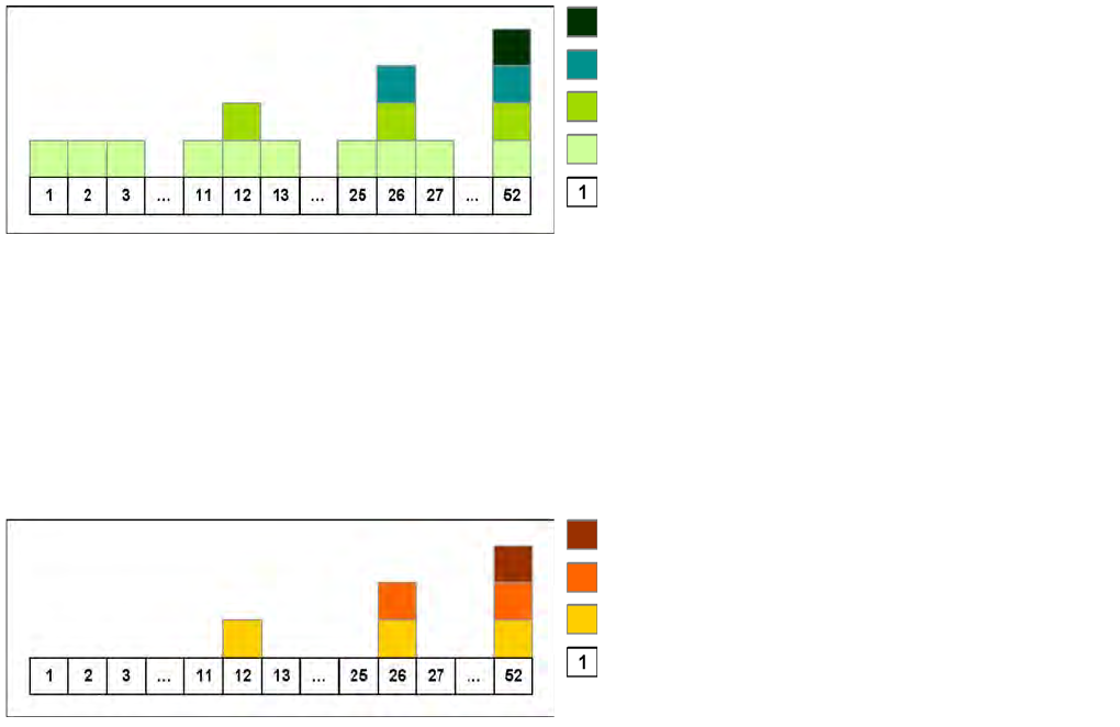
Annual maintenance tasks
6-monthly maintenance tasks
3-monthly maintenance tasks
Weekly maintenance tasks
Week
Annual maintenance tasks
6-monthly maintenance tasks
3-monthly maintenance tasks
Week
Introduction
Maintenance Notes Calculation of Maintenance Intervals
14 Maintenance Manual SIPLACE X Series
Calculat ion of Ma intenanc e Interval s
1.3.2 Calculation of Maintenance Intervals
The SIPLACE maintenance intervals are time-based and set according to the following conditions:
▪ Shift model: eight hours per shift, three shifts per day, five days a week and 50 weeks a year.
▪ Real placement performance in accordance with machine specifications
▪ Environmental and production conditions: see document "Conditions at Installation Site"
See also
4.1 Maintenance Intervals for Minor Maintenance [ ➙ 29]
5.1 Maintenance Intervals for Major Maintenance [ ➙ 63]
Adjusting the Maintenance Intervals to Actual Production Conditions
1.3.2.1 Adjusting the Maintenance Intervals to Actual Production Conditions
The maintenance status is calculated from the placement cycles, temperature and operating hours. The
status is shown as a progress bar (0 – 100 %).
Placement cycles for maintenance intervals:
▪ CPP head: 40 mill. placed components
▪ C&P20(A) head: 37.5 mill. placed components
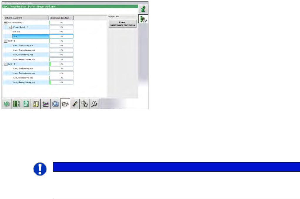
Some customers want to adjust maintenance intervals to
their actual environment and production conditions. A
maintenance monitor can also be accessed in the station
software for some assemblies (from SW703.02).
The maintenance monitor is available for the following
assemblies:
▪ CPP head (from SW703.02)
▪ C&P20(A) head (from SW704.xx)
▪ X and Y axis (from SW703.02, SX1/SX2/DX1/DX2
only)
NOTICE
Maintenance counter
► After maintenance has been completed, the maintenance counter needs to be manually
reset for the assembly concerned.