IPC-CC-830B.pdf - 第14页
in the individual test method, shall be made at temperature of 15 to 35°C [59 to 95°F], air pressure of 650 to 800 mil- limeters mercury [0.86 to 1.05 bar], and a maximum rela- tive humidity of 75%. Whenever the test con…

The control specimen shall be maintained at the reference
conditions at 25 ± 5°C [77 ± 9°F] and 50 ± 5% relative
humidity. The aged conformal coating shall be tack free to
touch.
There shall be no evidence of softening, chalking, blister-
ing, surface tack, cracking, loss of adhesion or reversion to
the liquid state. The clarity of the conformal coating must
remain suitable for the viewing of identification markings
and color codes used to identify components over which
the conformal coating is applied.
4 QUALITY ASSURANCE PROVISION
4.1 Responsibility for Inspection
Unless otherwise
specified, the conformal coating manufacturer is respon-
sible for all testing required in this standard. Test facilities
utilized must be agreed upon by all parties concerned and
may be those of the conformal coating manufacturer,
printed board assembler, user, or other mutually acceptable
test laboratory or combination thereof. The user reserves
the right to confirm that any of the specified inspection
procedures and test results conform to the prescribed para-
graphs.
4.2 Categories of Inspection
4.2.1 Qualification Inspection
Qualification inspection
allows a conformal coating manufacturer to assess the
properties of a conformal coating product on standardized
test vehicles using standardized test procedures. Variation
to the qualified formulation may or may not imply a
change of product, and may or may not be inspected for
qualification as a new product accordingly. See 4.4 for
definition of Product Change.
4.2.2 Qualification Retention Inspection The qualifica-
tion of a conformal coating product can be retained with
the satisfaction of qualification retention inspection.
4.2.3 Quality Conformance Inspection Quality con-
formance inspection shall be performed in order to express
consistency of material properties and process control.
Batches of conformal coating material shall be inspected
for compliance to the original requirements fulfilled during
qualification testing at a frequency adequate to assure con-
tinuing performance. Quality conformance inspection shall
be integrated into statistical process control programs or
other quality assurance programs (e.g., ISO 9000).
4.3 Frequency of Inspection
4.3.1 Qualification Inspection
Conformal coating quali-
fication inspection shall be performed once on each confor-
mal coating product.
4.3.2 Qualification Retention Inspection Conformal
coating qualification retention inspection shall be per-
formed once every two years on each conformal coating
product in order to prove consistent compliance to the
original qualification.
4.3.3 Quality Conformance Inspection Quality con-
formance inspection shall be performed for every batch of
conformal coating product. A batch shall consist of all con-
formal coating materials produced by one continuous run.
Batch identification is required (see 5.3).
4.4 Product Change The following variations in the for-
mulation of a conformal coating material originally quali-
fied by a supplier constitute a product change and shall
require a new name or product designation. The extent of
the name change is up to the supplier, but the change in the
name or designation must be prominently displayed and/or
obvious to the customer or end-user. Additional qualifica-
tion of the changed conformal coating formulation shall be
required. Qualification results of the original formula are
not to be assumed for the new formula:
• Changes exceeding ± 2% in the formula weight of any
nonvolatile ingredient from the ingredient’s original for-
mula weight.
• Addition or elimination of any nonvolatile ingredient.
• Changes in type or dye of pigment.
• Addition, deletion or change in composition of ‘‘inert’’
materials in the formulation.
The following do not constitute a change in formulation
and do not require additional qualification of the change,
but do require notification of the customer:
• Changes of less than ± 2% in the formula weight of any
nonvolatile ingredient from the ingredient’s original for-
mula weight.
• Addition, elimination or changes in any volatile ingredi-
ent (solvent) with less than 1% dried weight of residue in
the dried conformal coating (using recommended drying
procedures).
• Changes in the ratio of solids to volatile for viscosity
adjustment.
4.5 Test Equipment and Inspection Facilities Test and
measuring equipment and inspection facilities shall be of
sufficient accuracy, quality and quantity to permit the per-
formance of required inspection and shall be established
and maintained by or be accessible to all concerned parties.
The establishment and maintenance of a calibration system
to control the accuracy of the measuring and test equip-
ment shall be in accordance with ANSI/NCSL Z540-1 or
ISO 10012-1.
4.5.1 Standard Laboratory Conditions Test measure-
ments and conditions, unless otherwise specified herein, or
August 2002 IPC-CC-830B
5
Copyright Association Connecting Electronics Industries
Provided by IHS under license with IPC
Not for Resale
No reproduction or networking permitted without license from IHS
--```-`-`,,`,,`,`,,`---

in the individual test method, shall be made at temperature
of 15 to 35°C [59 to 95°F], air pressure of 650 to 800 mil-
limeters mercury [0.86 to 1.05 bar], and a maximum rela-
tive humidity of 75%. Whenever the test conditions must
be closely controlled in order to obtain reproducible results
for referee purposes, temperature, relative humidity and
atmospheric pressure conditions of 25 ± 3°C [77 ± 5.4°F],
40 to 60% RH, and 650 to 800 millimeters mercury [0.86
to 1.05 bar], shall be specified.
4.5.2 Permissible Temperature Variation in Environ-
mental Chambers
When chambers are used, specimens
under test shall be located only within the working area
defined as follows:
a. Reference temperature variation within working area:
The controls for the chambers shall be capable of main-
taining the temperature of any single reference point
within the working area within ± 2°C [± 3.6°F].
b. Spatial temperature variation within working area:
Chambers shall be so constructed that, at any given
time, the temperature of any point within the working
area shall not deviate more than 3°C [5.4°F] from the
reference point, except for the immediate vicinity of
specimens generating heat.
4.5.3 Reference Conditions Reference conditions as a
base for calculations shall be 25°C [77°F] for temperature,
760 millimeters mercury [1.01 bar] of air pressure, and a
relative humidity of 50%.
4.6 Inspection Routine Inspections shall be performed
in accordance with testing requirements defined in 3.2
thereof. Test specimens shall be prepared in accordance
with 4.7 and subjected to the procedure of test methods
listed in Table 3-1.
4.7 Inspection Sampling
4.7.1 Test Vehicles
Test vehicle to be used shall be in
accordance to specific test method as outline in Table 4-1.
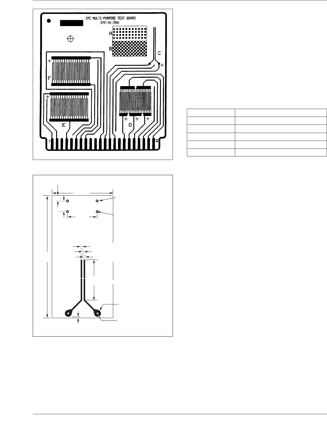
A IPC-B-25A Standard Test Board is illustrated in Figure
4-1. Test pattern to be used shall be as specified in test
method.
Test assemblies for temperature and humidity aging test
shall be made with the base material in accordance with
IPC-4101/21, IPC-4101/24, IPC-4101/25 or IPC-4101/26,
with tin plated or solder coated 17 µm copper ‘‘Y’’ shape
conductor, as illustrated in Figure 4-2. Test assemblies
shall contain two resistors, one with marking ink and one
with color code bars.
Glass plates to be used shall be standard laboratory glass
plates of 50 mm x 50 mm [1.97 in x 1.97 in] minimum
size.
Test strips for flammability testing shall be 13 mm [0.512
in] wide by 130 mm [5.118] long in accordance with UL
94 specification.
Tin panels shall be prepared in accordance with FED-STD-
141, Method 2012.
4.7.2 Sample Size The minimum number of test speci-
mens shall be as outlined in Table 4-1, or it shall be of
sufficient quantity to achieve statistical confidence required
by agreement between customer and supplier.
4.7.3 Preparation Prior to Coating The prepared test
vehicles shall be cleaned, handled and stored so that, at the
time of priming and/or coating, they meet the cleanliness
requirements of IPC-6012 (see 6.3 and 6.4).
Table 4-1 Test Vehicles and Sample Sizes
Paragraph Test to Run Test Method Test Vehicle
Number of
Specimen
3.5.2 Appearance Visual
Glass Plate*
4 coated,
1 uncoated
3.5.3 Fluorescence Visual under UV
4.7.4 Thickness ASTM-D-1005
3.5.4 Fungus Resistance IPC-TM-650
2.6.1.1
Glass Plate 4 coated
3.5.5 Flexibility IPC-TM-650
2.4.5.1
Tin Panel 4 coated
3.5.6 Flammability UL 94 HB UL 94 Test Strip 20 coated
3.6.1 Dielectric Withstanding Voltage IPC-TM-650
2.5.7.1
IPC-B-25A Test
Board
5 coated
3.7.1 Moisture and Insulation Resistance IPC-TM-650
2.6.3.4
IPC-B-25A Test
Board
4 coated,
1 uncoated
3.7.2 Thermal Shock IPC-TM-650
2.6.7.1
IPC-B-25A Test
Board
5 coated
3.7.3 Temperature and Humidity Aging
(Hydrolytic Stability)
IPC-TM-650
2.6.11.1
‘‘Y’’ shape test
assembly
5 coated
(1 as control)
* Same specimens are used for these inspections.
IPC-CC-830B August 2002
6
Copyright Association Connecting Electronics Industries
Provided by IHS under license with IPC
Not for Resale
No reproduction or networking permitted without license from IHS
--```-`-`,,`,,`,`,,`---
If and when a conformal coating manufacturer recom-
mends a primer for use with a conformal coating (as a sys-
tem), the primer shall be used in conjunction with the con-
formal coating material during qualification testing.
4.7.4 Coating The conformal coating shall be applied to
the test vehicles over the patterns and/or assemblies and
cured for the time and temperature recommended by the
manufacturer. Thickness shall be measured in accordance
with ASTM-D-1005 or by micrometer or indicator accurate
to 12.5 ± 2.5 µm [0.5 ± 0.1 mil]. For Type XY, the thick-
ness may be measured optically. A glass plate may be used
for referee in conformal coating thickness measurement.
For the purpose of qualification, qualification retention and
quality conformance inspection, the cured conformal coat-
ing on the test vehicle shall have a thickness as specified
in Table 4-2. For actual thickness requirements of applied
and cured conformal coating on a printed wiring assembly
product, refer to J-STD-001 or IPC-2221.
4.8 Failures One or more failures shall be cause for
repeating the failed test after the failure mode has been
determined and corrected. If the corrective action results in
a product change per 4.4, qualification of the changed
product shall be verified.
4.9 Inspection Reporting
4.9.1 Qualification Reporting
Because samples, equip-
ment, procedures and conditions may vary between loca-
tions or test systems, complete and precise reporting of
sample preparation, test details and verifying data is
required. Results of inspection shall be summarized in a
qualification inspection report, with classification attained
clearly indicated. An example of the format is shown in
Appendix A.
4.9.2 Qualification Retention Reporting Complete and
precise reporting of sample preparation, test details and
verifying data is required for qualification retention inspec-
tion. Results shall be compared with the original qualifica-
tion inspection results and reported accordingly. Results of
inspection shall be summarized in a qualification retention
inspection report. An example of the format is shown in
Appendix B.
4.9.3 Quality Conformance Reporting Results from the
quality conformance inspection shall be compared with the
original qualification inspection results and previous qual-
ity conformance inspection results. Results of inspection
shall be summarized in a quality conformance inspection
report. An example of the format is shown in Appendix C.
5 PREPARATION FOR DELIVERY
5.1 Containers
Containers for packaging shall be in
accordance with good commercial practices. Containers
IPC-830b-4-1
Figure 4-1 IPC-B-25A
IPC-830b-4-2
Figure 4-2 Test Coupon with ‘‘Y’’ Shape Pattern
75 mm
[2.95 in]
4.7 mm
[0.185 in]
38 mm
[1.50 in]
19 mm
[0.748 in]
6.30 mm [0.2480 in]
2.3 ± 0.13 mm DIA
[0.0906 ± 0.00513 in DIA]
Hole 0.75 ± 0.08 mm DIA
[0.0295 ± 0.0031 in DIA]
0.75 mm [0.0295 in MIN]
0.75 mm ± 0.08 mm [0.0295 in ± 0.0031 in MIN]
0.75 mm [0.0295 in MIN]
3.2 mm
[0.126 in]
25 ± 1.5 mm
[0.984 ± 0.0591 in MIN]
3.8 ± 0.13 mm DIA
[0.150 ± 0.00512 in DIA]
HOLE 1.3 ± 0.08 mm DIA
[0.051 ± 0.0031 in DIA]
Table 4-2 Thickness Requirements on Test Vehicle
Type of Coating Thickness
AR 25-75 µm [0.98-2.95 mil]
UR 25-75 µm [0.98-2.95 mil]
ER 25-75 µm [0.98-2.95 mil]
SR 50-200 µm [1.97-7.87 mil]
XY 12.5-50 µm [0.49-1.97 mil]
August 2002 IPC-CC-830B
7
Copyright Association Connecting Electronics Industries
Provided by IHS under license with IPC
Not for Resale
No reproduction or networking permitted without license from IHS
--```-`-`,,`,,`,`,,`---