00195374-0202_AI_LBO-D1D2_DE+EN.pdf - 第47页
Long bo ard option 2 Assembly instructions Long board op tion SIPLACE D1 / D2 06/2007 Edition 47 2.6.1 Adjusting the stopper unit s : Set the conveyor wid th to 200 mm. : Switch on the laser light barrier via the I/O fun…
2 Assembly instructions Long board option SIPLACE D1 / D2 Long board option
06/2007 Edition
46
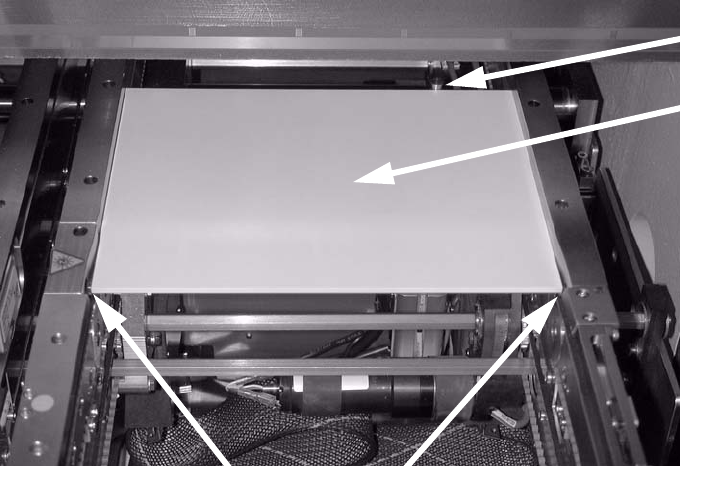
: Fit the cover over the conversion board (6 screws) beneath the output conveyor belt.
Cover
2
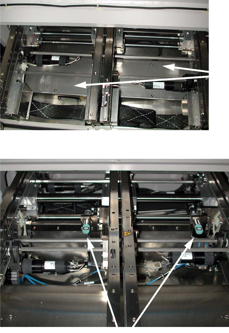
The stoppers should now look as follows (example of the dual conveyor): 2
Stopper
2
: Switch the placement machine on at the main switch and start the SITEST program.
Long board option 2 Assembly instructions Long board option SIPLACE D1 / D2
06/2007 Edition
47
2.6.1 Adjusting the stopper units
: Set the conveyor width to 200 mm.
: Switch on the laser
light barrier via the I/O functions in SITEST (see section 1.7).
: Use the I/O functions to extend the stopper.
: Check that the distance between the laser light barrier and the stopper is 150 mm
using
th
e "LBO D1/D2 assembly gauge" (03049211-xx).
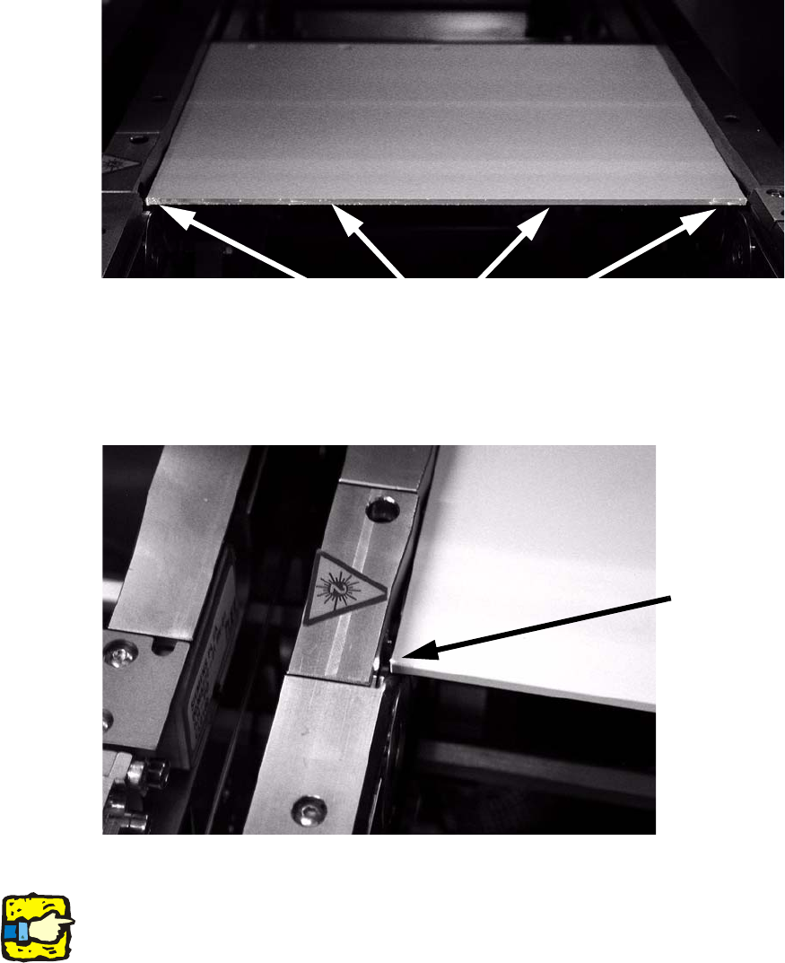
: Place the adjusting g
auge in the conveyor and push it against the stopper.
The gauge must lie against the stopper and the st
ationary conveyor side wall.
Adjusting
gauge
Stopper
Laser light barriers
2
2
: Place the adjusting gauge in the conveyor and push it against the stopper.
The gauge must lie against the stopper and the st
ationary conveyor side wall.
2
2
2
2
2
2
2 Assembly instructions Long board option SIPLACE D1 / D2 Long board option
06/2007 Edition
48
: Check whether the laser beam can be seen on the entire front edge of the adjusting gauge. If
this is not the case, adjust the stopper so that the laser beam is visible.
: To do this, loosen the fixing screws on the stoppe
r, align the stopper and then tighten the
screws once more.
Laser dots must be visible.
2
The adjusting gauge should therefore not lie inside the light barrier because it will interrupt the
beam on one side: 2
The beam does not
fall along the adjust-
ing gauge.
2
: Adjust all the stoppers on all the conveyor tracks.
2
The adjustment must be repeated whenever the stopper unit is dismantled and refitted. 2
2