00196715-01_IM_SSW_704_DE_EN.pdf - 第22页
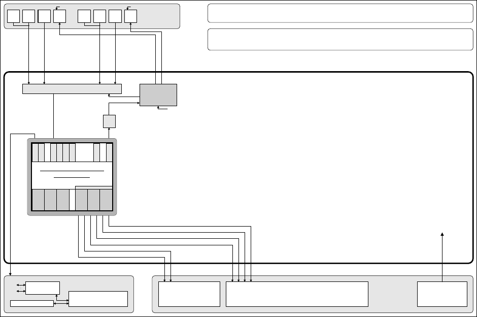
Installation Manual, Station Software Version 704.01 04/2010 Edition The following diagram shows the hardware component s of the computer system for the SIPLACE SX1/SX2 machine in one-computer operation: Fig. 4-3: Hardwa…
Installation Manual, Station Software Version 704.01 04/2010 Edition
Camera system
for 2 placement areas with 4 placement heads
with component Vision and board position recognition
PS
Power supply
Production line
LAN (hub)
Customer LAN
1 2
CAN bus
Remote control
Machine
Structure of the computer unit and its interfaces
SIPLACE X2, X3, X4, X4I
Basic set-up with 2 x Box PC 627B Serie / SW: 704 / 2-computer operation
Programming system
SIPLACE Pro
Programming system
and external networks
LAN
Computer unit
Video multiplexer
with splitter
VGA VGA
VGA VGA
to Box PCs 627B
+5 V
Output
DC/DC
converter
Input
Touch
screen 1
User
interface
Touch
screen 2
Keyboard
1
Keyboard
2
Mouse
1
Mouse
2
Monitor
1
Monitor
2
USB hub
+5 V
+24 V+24 V
to
video multiplexer
and
USB hub
+24 V
+48 V +5 V
Adapter
DVI-I
to VGA
Core 2 Duo T7400 / 2,16 GHz, HSP 1 GB
Vision computer
SIMATIC Box PC 627B
P C I - B u s
Hot-
link
PCI
Hot-
link
PCI
C
O
M
1
D
V
I
-I
U
S
B
1
U
S
B
2
U
S
B
3
HD
40 GB
L
A
N
1
U
S
B
4
L
A
N
2
Connection:
compact
flash drive
Adapter
DVI-I
to VGA
Pentium M 760 2 GHz, HSP 1 GB
Machine computer
SIMATIC Box PC 627B
P C I - B u s
C
O
M
1
D
V
I
-I
U
S
B
1
U
S
B
2
U
S
B
3
HD
40 GB
L
A
N
1
U
S
B
4
L
A
N
2
Connection:
compact
flash drive
CAN
1 2
PCI
COM 168
PCI-...
Core 2 Duo T7400 / 2,16 GHz, HSP 1 GB
Fig. 4-2: Hardware components of the computer system for the SIPLACE X-series in two-computer operation (block diagram)
21 of 60
Installation Manual, Station Software Version 704.01 04/2010 Edition
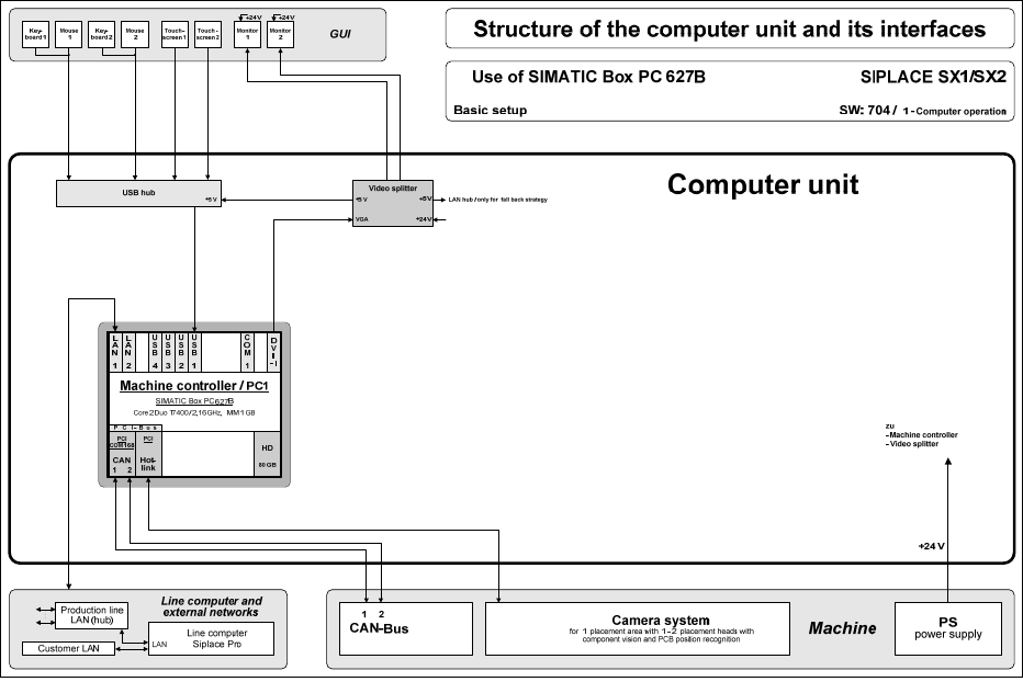
The following diagram shows the hardware components of the computer system for the SIPLACE
SX1/SX2 machine in one-computer operation:
Fig. 4-3: Hardware components of the computer system for SIPLACE SX1/SX2 in one-computer operation (block diagram)
22 of 60
Installation Manual, Station Software Version 704.01 04/2010 Edition
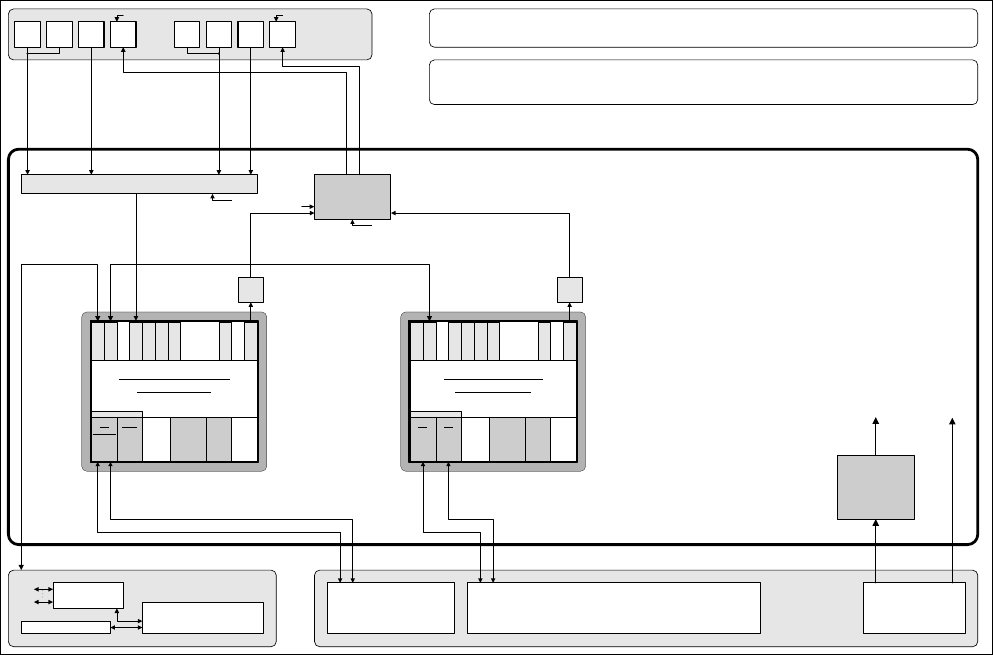
The following diagram shows the hardware components of the computer system for the SIPLACE X2, X3,
X4 and X4I machines in one-computer operation:
Camera system
for 4 placement areas with 4 placement heads
with comp. vision and pcb position recognition
PS
Power supply
Production line -
LAN (hub)
Customer LAN
1 2
CAN bus
Remote control
Machine
Structure of the computer unit and its interfaces
Use of SIMATIC Box PC 827B SIPLACE X-Series
Basic setup Serial / SW: 704 / 1 – computer operation
Line computer
Siplace Pro
Line computer and
external networks
LAN
Computer unit
Touch
screen 1
User
interface
Touch
screen 2
Keyboard
1
Keyboard
2
Mouse
1
Mouse
2
Monitor
1
Monitor
2
USB hub
+5 V
+24 V+24 V
to
- Box PC 827B
- Video splitter
+24 V
Video
splitter
.
+24 V
Adapter
DVI-I
to VGA
VGA
+5 V
Core 2 Duo T7400 / 2,16 GHz, HSP 2 GB
Machine controller R1
SIMATIC Box PC 827B
P C I b u s
C
O
M
1
D
V
I
-I
U
S
B
1
U
S
B
2
U
S
B
3
HD
80 GB
L
A
N
1
U
S
B
4
L
A
N
2
Connec-
tion:
Compact
Flash
drive
CAN
1 2
PCI
COM 168
DVD
drive
2-channel
Hot
link
PCI
2-channel
Hot
link
PCI
Fig. 4-4: Hardware components of the computer system for the SIPLACE X-series in one-computer operation (schematic block
diagram)
For the SIPLACE SX4 machine the hardware components of the computer system in one-computer
operation are the same as displayed in figure 4-4 with the following variation:
- No USB hub
23 of 60