Printer 710_810 v8 High Throughput Conveyor Module.pdf - 第8页
HIGH THROUG HPUT CONVEY OR (HTC) MOD ULE ADJUS TMEN TS AND SE TTINGS 17.8 Technical Reference Manual Chapter Issue 3 Oct 06 Auxiliary Conveyor Sensors Heavy Board Position al Adjustment If heavy boards are being pri nted…

HIGH THROUGHPUT CONVEYOR (HTC) MODULE
ADJUSTMENTS AND SETTINGS
Chapter Issue 3 Oct 06 Technical Reference Manual 17.7
14. Select Adjust, the following window is displayed:
15. Using the Next, Previous, Incr. and Decr. keys, set the Board Width to
50mm.
16. Select Exit.
17. Select Drive Rail To Board Width, the rear rail moves to the new board
width.
18. Repeat Steps 10 and 11 for setting the vane at the 50mm width. Lock the
adjusting screws.
19. Select Home Rail Width.
20. Select Run Diagnost, the rear rail moves to the home position.
21. Repeat Steps 10 and 11 at the home position, adjust vanes if necessary.
22. Select Cycle Rails.
23. Select Run Diagnost, ensure the sensors LED are On over the full travel of
the rail.
Rail System Test Parameters
BOARD WIDTH
CYCLE COUNT
250.0
50
mm
Cycles
HIGH THROUGHPUT CONVEYOR (HTC) MODULE
ADJUSTMENTS AND SETTINGS
17.8 Technical Reference Manual Chapter Issue 3 Oct 06
Auxiliary Conveyor Sensors
Heavy Board
Positional
Adjustment
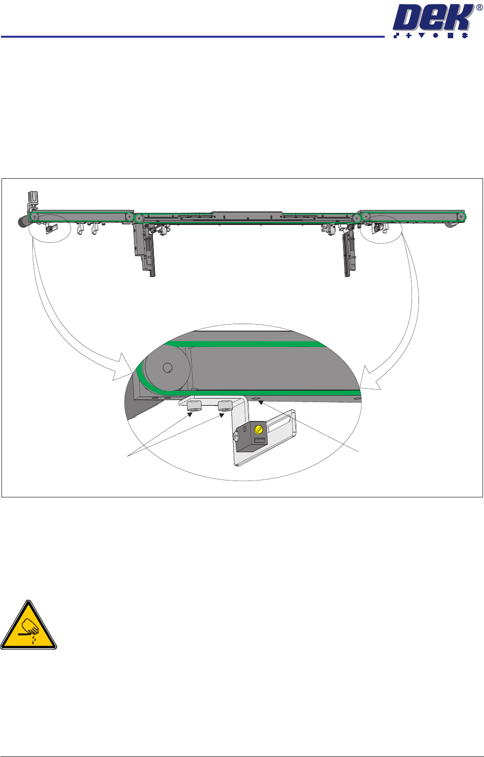
If heavy boards are being printed and causing damage to the conveyor board
stops, adjustment of the position of the sensor can be carried out to minimise
this effect. To adjust the position of the sensor carry out the following:
1. Power down the machine.
2. Remove the sensor mounting bracket screws from the underside of the front
rail of the auxiliary conveyors.
3. Reposition the sensor mounting bracket by utilizing the additional mounting
hole in the front rail.
4. Refit the sensor mounting bracket securing screws.
5. Power up and run the machine, checking for correct operation of the sensor.
Board Optos
WARNING
BOARD CLAMPS. EXTREME CARE MUST BE EXERCISED WHEN WORKING IN
THE TOOLING AREA OF THE MACHINE TO AVOID INJURY. THE FOILS ON THE
FRONT AND REAR BOARD CLAMPS ARE VERY SHARP.
Positional
Adjustment
If the current product has an unsymmetrical board outline, the position of the
board optos can be adjusted to cater for these products. To adjust the position
of the sensor carry out the following:
1. Power down the machine.
Rear View of Front HTC Rail
Mounting Bracket Securing
Bolts (in 2 positions)
Additional Mounting Hole
HIGH THROUGHPUT CONVEYOR (HTC) MODULE
ADJUSTMENTS AND SETTINGS
Chapter Issue 3 Oct 06 Technical Reference Manual 17.9
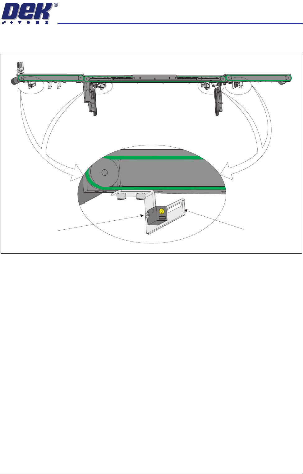
2. Loosen sensor pan head mounting bolt.
3. Adjust the position of the sensor as required.
4. Tighten the securing bolt.
5. Power up and run the machine, checking for correct operation of the sensor.
NOTE
Further positional adjustment of the sensor is possible by means of swopping
the side the sensor is fitted to the sensor attachment bracket.
Rear View of Front HTC Rail
Sensor Pan Head
Mounting Bolt
Sensor Attachment
Bracket