00193351-06_RI_Vacuum_pump_de en.pdf - 第49页
SIPLACE HS-50/HS-60/D4/S-25HM/S-27HM/HF -Series 2 Retrofit instructions for vacuum pump 07/2011 Edition 47 : Open the compressed air stopcock. : Close the com pressed air su pply door . : Close the covers of the placemen…
2 Retrofit instructions for vacuum pump SIPLACE HS-50/HS-60/D4/S-25HM/S-27HM/HF-Series
07/2011 Edition
46
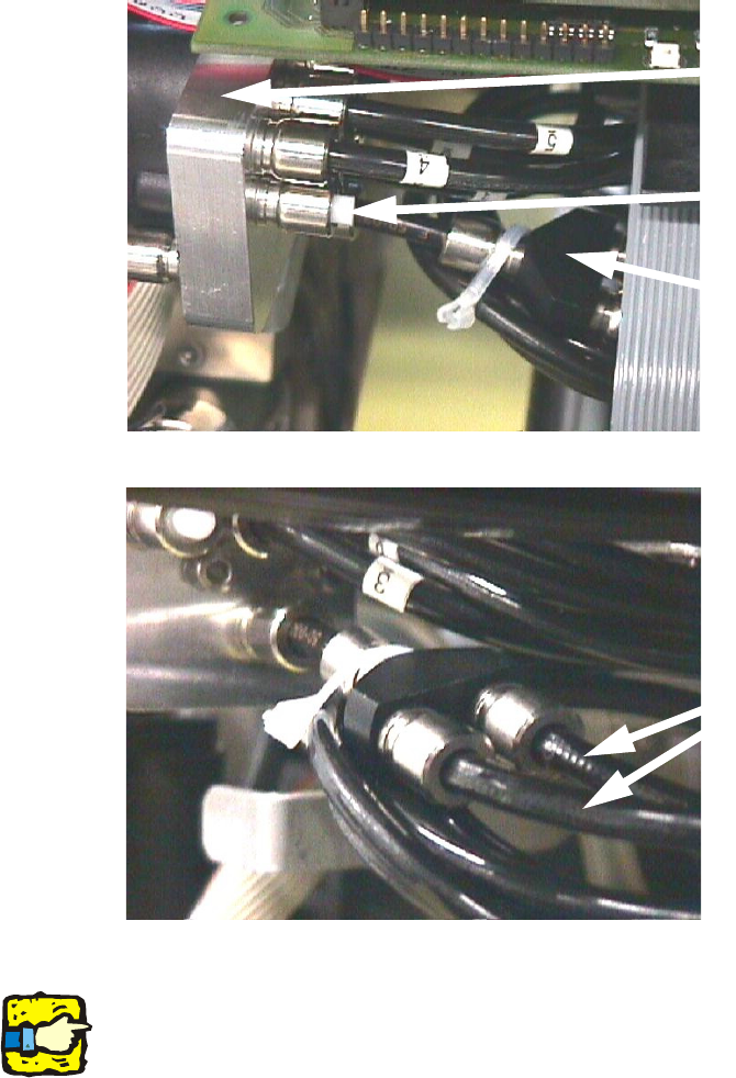
Layout of hoses S-25 HM 2
2
2
2
2
Do not crack the compressed air hoses!! 2
2
2
2
2
2
2
New vacuum generator
Blind plug
Y-joint for hoses
1 and 2
Cable nos. 1 and 2
Holding circuit
The marked hoses 1 and 2 are
connected to the newly installed
PUN 8 hose

SIPLACE HS-50/HS-60/D4/S-25HM/S-27HM/HF-Series 2 Retrofit instructions for vacuum pump
07/2011 Edition
47
: Open the compressed air stopcock.
: Close the compressed air supply door.
: Close the covers of the placement machine and connect it to the supply voltage.
: Check the air pressure for the stopper at the pressure gauge. The air pressure must be at
2.3 bar.
: For adjusting the forced air valve use a nozzle type 904.
: Adjust the forced air valve for:
the placement cicuit to 150 ± 50 mbar
the rejection circuit to 250 ± 50 mbar.
2
2
For checking the vacuum values see section 2.7.2, page 53. 2
2
2
2
2
2
2
2
2
2
2
2
2
2
2
2
2
2
2 Retrofit instructions for vacuum pump SIPLACE HS-50/HS-60/D4/S-25HM/S-27HM/HF-Series
07/2011 Edition
48
2.5 SIPLACE HF
2.5.1 Necessary parts
Connection kit vacuum pump HF: (Item no. 00119696-01) 2
Vacuum pump (item no. 00119794-xx) 2
2.5.2 Necessary tools
Set of Allen keys 2
Set of flat wrenches 2
Philips screwdriver 2
2.5.3 Modification of compressed air supply holding and placement circuit
: Switch the placement machine off at the main switch.
: Open the door of the compressed air supply.
: Close the main compressed air stopcock.
: Close the stopcock.
: Remove both 12 mm compressed air hoses at both stopcocks.
: Screw the new compressed air distributors onto the left side of the housing.