00193351-06_RI_Vacuum_pump_de en.pdf - 第56页
2 Retrofit instructions for vacuum pump SIPLACE HS-50/HS-60/D4/S-25HM/S-27HM/HF-Series 07/2011 Edition 54 The reas on for not r eaching the se values mo stly is a hose in the area of placement he ad which is nit attached…

SIPLACE HS-50/HS-60/D4/S-25HM/S-27HM/HF-Series 2 Retrofit instructions for vacuum pump
07/2011 Edition
53
2.7 Final tasks
2.7.1 Check the pre-conditions for switching on
2
Before switching on make the following checks to avoid injury and damage. 2
2
2
Switch on always first the vacuum pump, then the placement machine! 2
Ensure before engaging compressed air, that 2
: all hoses / -connections are connected and allocated correctly.
: the pre-conditions for switching on vacuum pump and placement machine are followed, as
described in the user manual.
2.7.2 Check of holding circuit
2.7.2.1 Check vacuum system of holding circuit for pressure tightness
Vacuum measuring with external pressure measurement tool at the measuring point of the va-
cuum distributor and then an open nozzle at the holding circuit on the placement head. 2
The difference should not be higher than 20-30 mbar, if the system is tight. 2
At vacuum check of holding circuit a different value is possible, if vacuum board has an offset.
Therefore measurements at head an vacuum distributor should be done with the same measuring
tool. 2
2
The absolute vacuum value of holding circuit with closed nozzles is lower (30-50 mbar ) with
vacuum pump than with venturi nozzle in pickup circuit (measured with an external measurement
tool at open nozzle in pickup circuit and holding circuit) .
This difference is acceptable, if at a height of 521 m NN (height of System acceptance of Siemens
L&A Munich) at least 800 mbar can be achieved. 2
2
2
2
2
2
2
2

2 Retrofit instructions for vacuum pump SIPLACE HS-50/HS-60/D4/S-25HM/S-27HM/HF-Series
07/2011 Edition
54
The reason for not reaching these values mostly is a hose in the area of placement head which is
nit attached till stop position: 2
: Impress all hoses with the hose pliers and repeat the measurement of vacuum.
2.7.2.2 Check of the air flow of the vacuum system holding circuit
The correct air flow can be controlled by means of the vacuum curves: 2
: Remove the nozzles from the placement head (to achieve maximum air flow), open in SITEST
all segments in pickup position one after each other and turn it with star cycle into the holding
circuit.
: The vacuum measurement in the holding circuit shows with every additional opened nozzle a
vacuum decrease of 60 - 90 mbar.
2
2
With six open nozzles the vacuum could reduce, e.g. from 880 mbar to 520 mbar (reduction
360 mbar).
With six C&P placement heads at two placement machines on two vacuum pumps the decrease
is higher, at only one placement machine lower (four or two C&P placement heads). 2
2
2
2
SIPLACE HS-50/HS-60/D4/S-25HM/S-27HM/HF-Series 2 Retrofit instructions for vacuum pump
07/2011 Edition
55
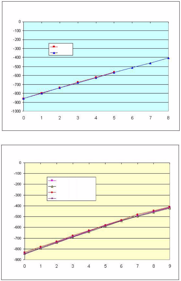
Vacuum curves 2
2
2
2
Vacuum [mbar]
Number of open nozzles
Gantry 1
Gantry 2
Vacuum curve for S27HM with ELMO 2BL 1 1000 vacuum pump and 720 nozzles
Gantry 1: 6-segment head / Gantry 2: 12-segment head
Relative Vacuum [mbar]
Number of open nozzles
Vacuum curve for HS60 with ELMO 2BL 1 1000 vacuum pump and 914 nozzles
12-seg. head, gantry 1
12-seg. head, gantry 2
12-seg. head, gantry 3
12-seg. head, gantry 4