00190935-01.pdf - 第38页
Pipettenwechsler Siplace 80S15/F3/S20/F4 Nozzle Changer Nachrüstanleitung/Retrofitting Instructions Ausgabe/Edition 03/97 Seite/Page 38 von/of 44 Figure 10: Connections on the revolver head nozzle changer • Remove the fe…
Nachrüstanleitung/Retrofitting Instructions Pipettenwechsler Siplace 80S15/F3/S20/F4 Nozzle Changer
Ausgabe/Edition 03/97
Seite/Page 37 von/of 44
1.5.2 Fitting the Siplace 80S20/F4
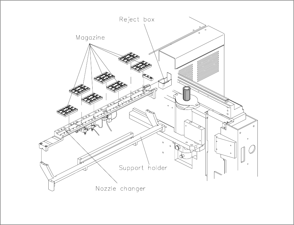
Figure 9: Side view of the support holder with nozzle changer
Pipettenwechsler Siplace 80S15/F3/S20/F4 Nozzle Changer Nachrüstanleitung/Retrofitting Instructions
Ausgabe/Edition 03/97
Seite/Page 38 von/of 44
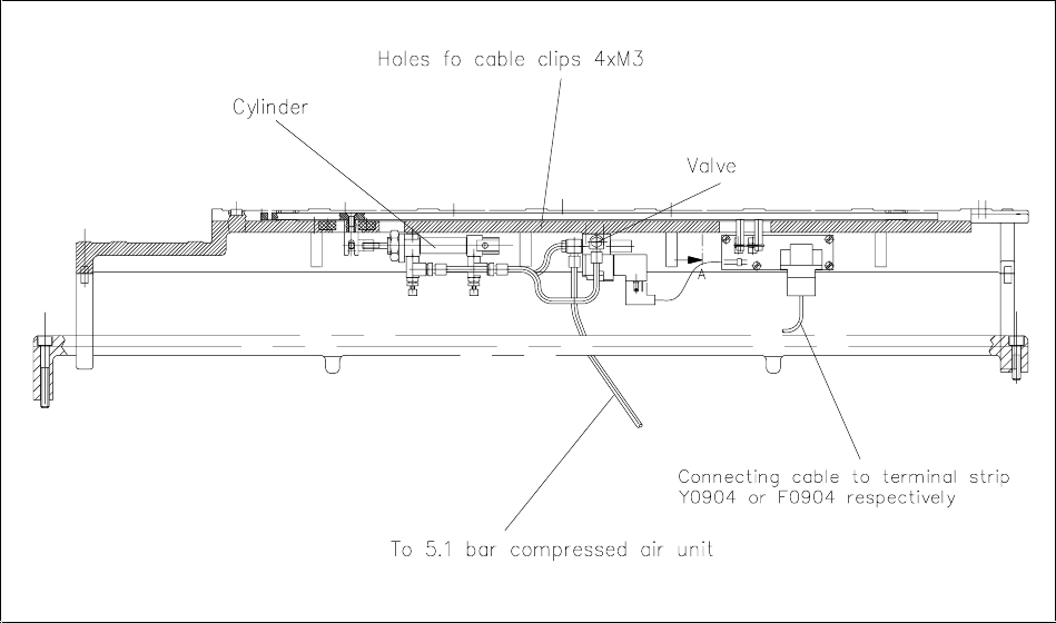
Figure 10: Connections on the revolver head nozzle changer
• Remove the feeders from the components table on the relevant side of the machine.
• Attach the compressed air supply to the nozzle changer valve.
• Attach the connecting cable Y0553-W2 or Y0553-W1 to the nozzle changer control board
(see figure 10).
Nachrüstanleitung/Retrofitting Instructions Pipettenwechsler Siplace 80S15/F3/S20/F4 Nozzle Changer
Ausgabe/Edition 03/97
Seite/Page 39 von/of 44
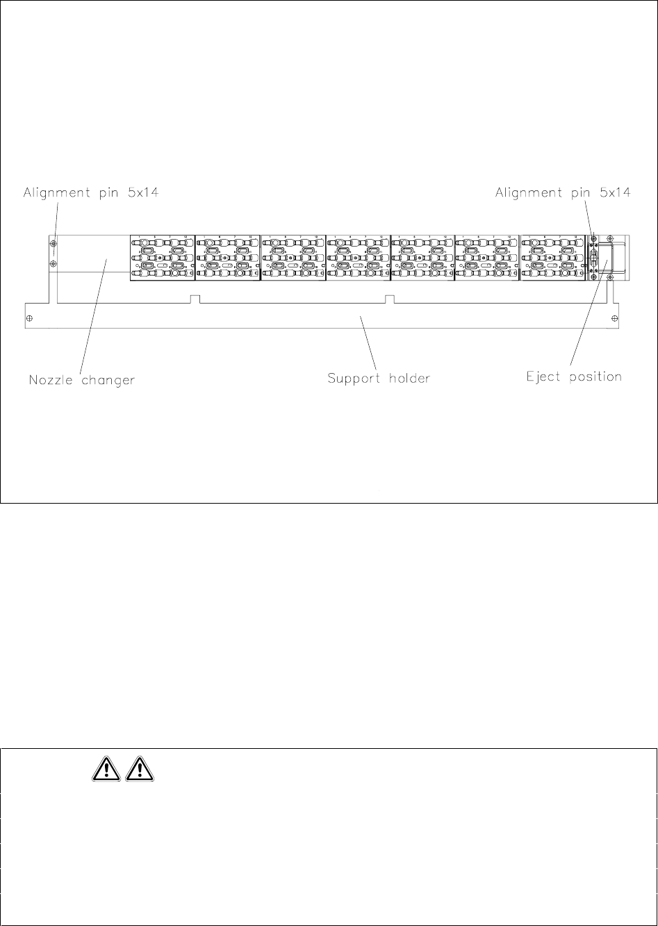
Figure 11: Fitting the nozzle changer
• Insert the alignment pins into the support holder (see figure 11).
• Using the cable clips, fix the connecting cable and the compressed air hose to the nozzle changer at
the holes provided.
• Screw the nozzle changer onto the support holder (see figure 11).
1.5.2.1 Laying the cables and compressed air hoses
Please note
On all the machines, the cable and the compressed air hose are already installed and have been pulled
in. However, there are special retrofit kits for certain machines in which the cable and compressed air
hose have not been fitted. It is only for these retrofitting operations that the retrofit kit includes the cable
and compressed air hose, which will have to be fitted. It is only in these cases that the work described
in sections 1.5.1.1, 1.5.1.2 and 1.5.1.3 (Siplace 80S15/F3) has to be carried out.