00198532-01_SM_MeasurementFeeder_EN.pdf - 第12页
2 Replacing spare parts 2.3 Rear sliding Guide 12 Service Manual SIPLACE MeasurementFeeder X 02/2020 2.3 Rear sliding Guide Required spare part Fig.2: Sliding guide, back Feeder module Item no. Designation MeasurementFe…
2 Replacing spare parts
2.2 Front sliding guide / sliding foil
Service Manual SIPLACE MeasurementFeeder X 02/2020 11
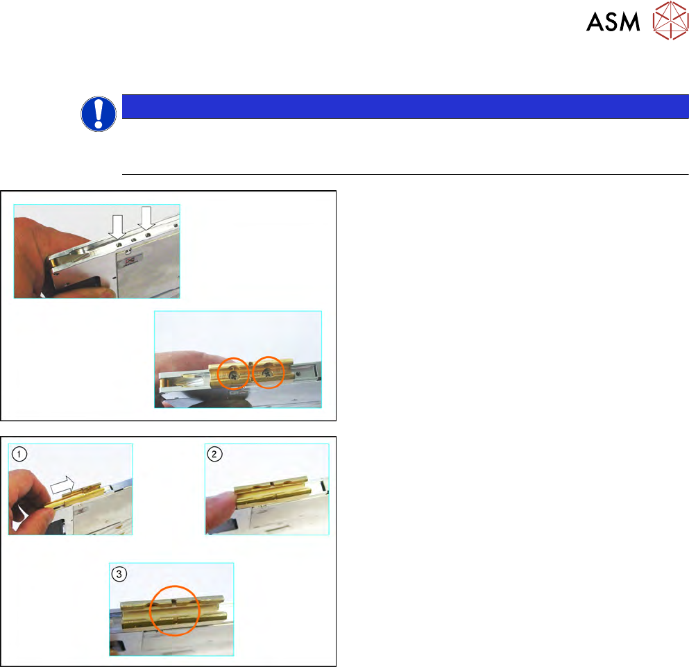
2.2.2 Fitting the Front Sliding Guide
NOTICE
The pickup window must be fitted
To prevent damage to the sprocket wheel and the reject device, make sure that the pickup
window is fitted for this work.
► Insert the sliding guide - as shown in the diagram
- into the groove on the drive carrier.
► Position the front sliding guide so that you can
see the holes for the screws through the sliding
guide.
► Fix the sliding guide to the feeder module with
the 2 Phillips head screws (M3x10mm).
► Press the sliding foil slightly together.
► Push the sliding foil from the front into the sliding
guide, until it engages audibly.

2 Replacing spare parts
2.3 Rear sliding Guide
12 Service Manual SIPLACE MeasurementFeeder X 02/2020
2.3 Rear sliding Guide
Required spare part
Fig.2: Sliding guide, back
Feeder module Item no. Designation
MeasurementFeederX 03003994-xx
03119317-xx
00328251-xx
Sliding guide / back L200
ISO 14585 - ST2.9x9.5-F-St,FeZn (3x)
SN 213307-H-M2.5 x 8-A2-70 (1x)
Required tools
●
TORX screwdriver 0.6 Nm, size T8
2 Replacing spare parts
2.3 Rear sliding Guide
Service Manual SIPLACE MeasurementFeeder X 02/2020 13
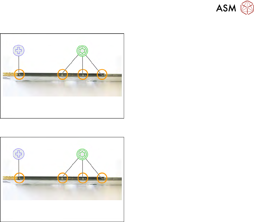
2.3.1 Removing the Sliding Guide
► Turn the feeder module so that its underside is at
the top.
► Remove the Phillips screw from the left side.
► Remove the three TORX screws from the right
side.
► Lift the gliding slide upwards and off.
2.3.2 Fitting the Sliding Guide
► Turn the feeder module so that its underside is at
the top.
► Fit the guiding slide – as illustrated – to the un-
derside of the feeder module.
Observe the arrangement of the drilled holes in
the guiding slide.
► Push the guiding slide, as shown, to the left
(front) towards the front guiding slide, as far as
the stop.
► Now lower the two snap tabs of the guiding slide
into the openings provided on the underside of
the feeder module.
► Fasten the sliding guide on the left side to the
feeder module, using the Phillips screw "ISO
7045 - M2.5 x 6-A2-50-H" tightened to 0.6N.
► Use the 3 TORX screws to fix the guiding slide
on the right side with 0.6Nm to the feeder mod-
ule.