00198532-01_SM_MeasurementFeeder_EN.pdf - 第24页
2 Replacing spare parts 2.7 Measurement board 24 Service Manual SIPLACE MeasurementFeeder X 02/2020 2.7 Measurement board Required spare part Fig.6: Measurement board cpl Feeder module Item no. Designation MeasurementFe…
2 Replacing spare parts
2.6 Contact module
Service Manual SIPLACE MeasurementFeeder X 02/2020 23
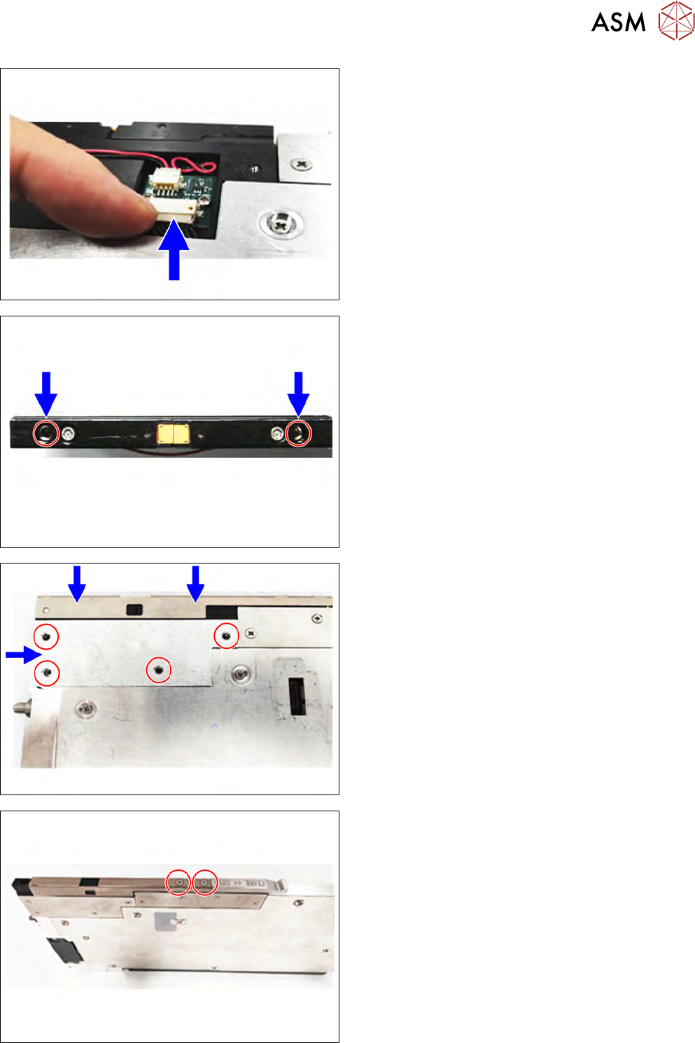
► Connect the contact module to the connector.
► Put a drop of Loctite 243 on the two marked
screws (M3X12 Allen screw, 03042544).
► Tighten the two screws on the top of the contact
module.
► Align the protective plate.
► Tighten the four cross head countersunk screws
(ISO7046-2 M2.5X6, 03023228-xx) to hold the
protective plate.
Put the contact module cover on the top of the contact
module as shown.
► Tighten the two cross head countersunk screws
(ISO7046-2 M3X6, 03023238-xx) to hold the con-
tact module cover.
2 Replacing spare parts
2.7 Measurement board
24 Service Manual SIPLACE MeasurementFeeder X 02/2020
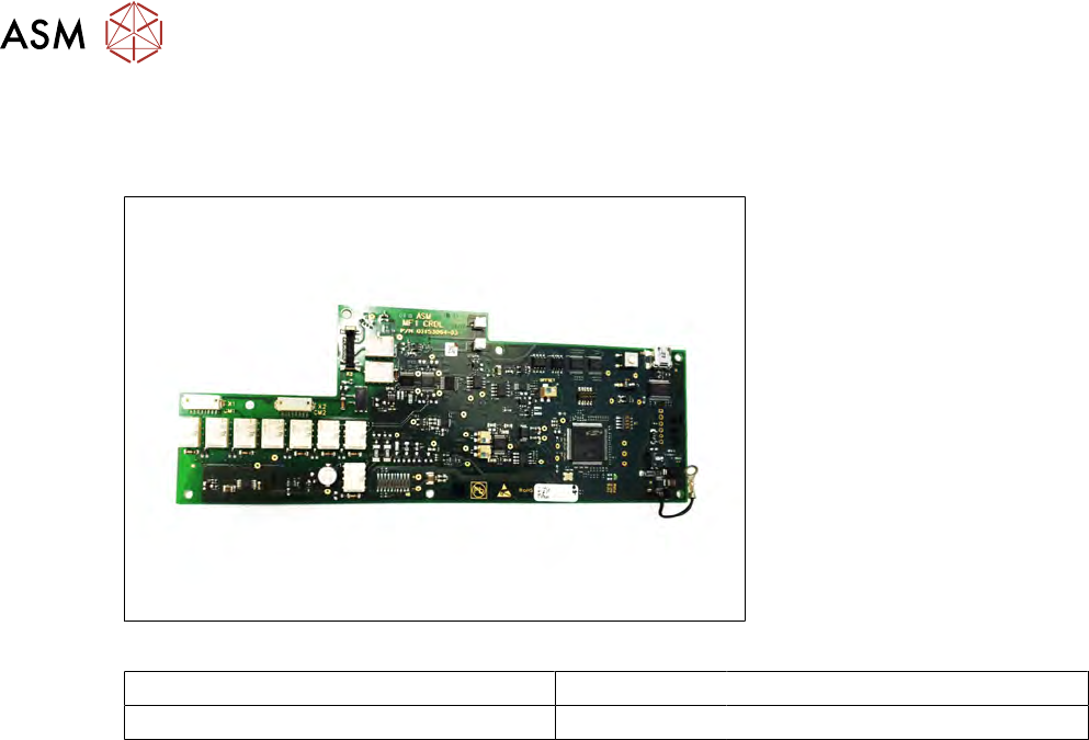
2.7 Measurement board
Required spare part
Fig.6: Measurement board cpl
Feeder module Item no. Designation
MeasurementFeeder X 03210586-xx Measurement board cpl
Required tools
●
Flat-bladed screwdriver
●
Phillips screwdriver
●
Spanner, size 5mm
●
Loctite 243
2 Replacing spare parts
2.7 Measurement board
Service Manual SIPLACE MeasurementFeeder X 02/2020 25
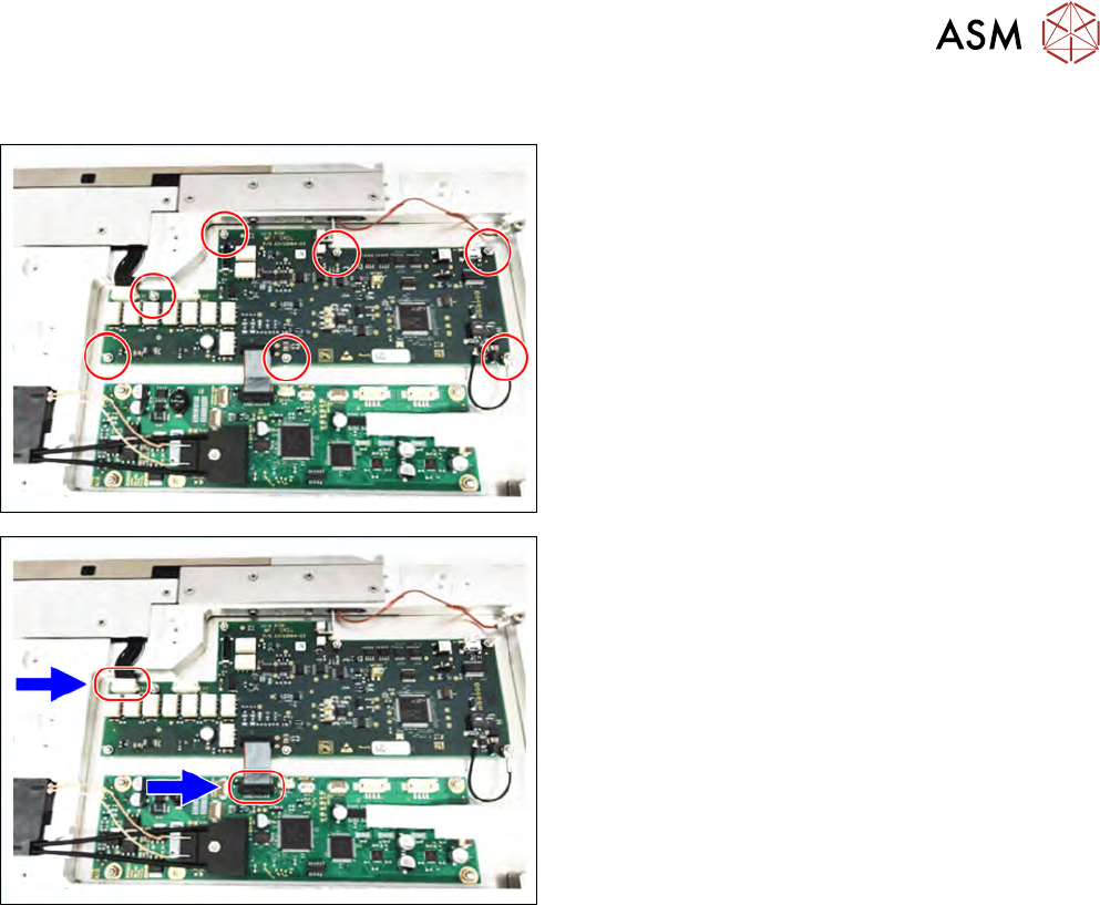
2.7.1 Removing the measurement board
► Remove the left side cover (see 2.4.1 "Removing
the side cover" [}15]).
► Loosen the seven nuts marked in the figure using
a spanner size 5mm.
► Disconnect to two connectors marked in the fig-
ure.
► Remove the measurement board.