00198532-01_SM_MeasurementFeeder_EN.pdf - 第27页
3 Synchronization Service Manual SIPLACE MeasurementFeeder X 02/2020 27 3 Synchronization Required tools Fig.7: SIPLACE XFeeder Verification System (XFVS), item no. 03126186-xx Synchronizing the MeasurementFeederX W…
2 Replacing spare parts
2.7 Measurement board
26 Service Manual SIPLACE MeasurementFeeder X 02/2020
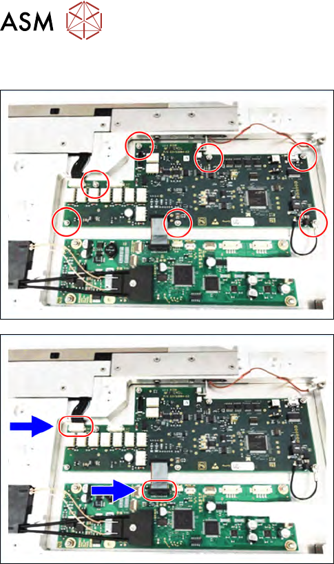
2.7.2 Fitting the measurement board
► Align the measurement board to the Measure-
mentFeeder.
► Put a drop of Loctite 243 on the top of every
single thread marked in the figure right before
tightening the nut.
► Tighten the seven nuts (M2 X2.5, 03008160-xx)
marked in the figure using a spanner size 5mm.
► Connect to two connectors marked in the figure.
► Fit the left side cover to the feeder (see 2.4.2 "Fit-
ting the side plate" [}16]).
3 Synchronization
Service Manual SIPLACE MeasurementFeeder X 02/2020 27
3 Synchronization
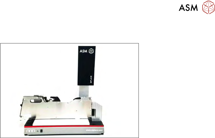
Required tools
Fig.7: SIPLACE XFeeder Verification System (XFVS), item no. 03126186-xx
Synchronizing the MeasurementFeederX
When the MeasurementFeederX is power up, the system will compare serial number of the
contact module to the information stored in the EEPROM of the measurement board. The
MeasurementFeederX will not be able to function if the information does not match.
After changing the contact board and/or the measurement board, the MeasurementFeederX must
be inserted to the SIPLACE XFeeder Verification System (XFVS) to do a synchronization.
For further information please refer to the user manual of the X Feeder Verification System
(itemno. 00198272-XX).

3 Synchronization
28 Service Manual SIPLACE MeasurementFeeder X 02/2020