00190585-04.pdf - 第62页
SIPLACE 80 F4/F5 1 Retrof itting Instructions for Coplanarity Option Edition 05/99 1.8 Configuring the Option (at Line Computer and Station Computer) and Putting It into Service 1 - 26 NOTE For th e executio n of t est c…
1 Retrofitting Instructions for Coplanarity Option SIPLACE 80 F4/(F4-6)/F5
1.8 Configuring the Option (at Line Computer and Station Computer) and Putting It into Service Edition 05/99
1 - 25
see Fig. 1.6.1 -> 5.
- In case of machines with a
single conveyor: Distance washers were installed at the
above location ( = incorrect).
- Focus outside of tolerances
Possible causes:
- Calibration tool damaged or not picked up.
- In case of V 403.04: Z-position for coplanarity sensor incorrectly entered in the file real.ma.
- Diameter of calibration tool not within tolerances
Possible cause:
- Nozzle projects over calibration tool -> Wrong nozzle picked up (= not 417).
● If desired, actuate the “Display” button to see the measured values.
● Terminate the menu “COPLANARITY”. Terminate the SITEST program.
● Answer “YES” to the question being displayed: “Store the data?”
The offset values for X, Y and Z are entered in the
real.ma data under coplanarity_2_x /.... _y /.... _z .
● Press EMERGENCY OFF and remove the calibration tool.
● As the final step, check whether the IC camera and flip-chip camera function.
1.8.8 In Case of Problems or Errors:
Check Position of Coplanarity Sensor (>
V 403.xx)
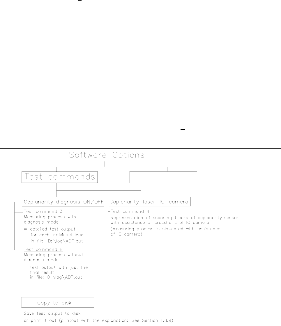
Fig. 1.8.1 Menu Structure “Software Options” (Station Computer)

SIPLACE 80 F4/F5 1 Retrofitting Instructions for Coplanarity Option
Edition 05/99 1.8 Configuring the Option (at Line Computer and Station Computer) and Putting It into Service
1 - 26
NOTE
For the execution of test commands 3 and 8 see Section 1.8.9, Run Data Protocol (German: ADP).
You can utilize test command 4 (see Fig. 1.8.1) to check whether the laser track strikes the leads.
- The component to be measured is optically centered after test command 4 is called up. Instead of being
moved over the coplanarity sensor, it is moved over the camera., i.e., the
measurement process is there-
fore
simulated.
- The midpoint of the IC camera (crosshairs) corresponds to the focus point of the coplanarity sensor.
1.8.8.6 Procedure (> V 403.xx)
● Execute only in case of software version 403.04 -> D:\DAT\SST.MA, speed factor:
If this value is > 200 reduce the value to 200 (= higher accuracy).
CAUTION O
It is not permissible to change the entered speed factor in the case of V 404.xx.
● Restart the machine to transfer the revised data.
● Activate the submenu “Test command 4” in the menu “Software options”
● Turn the cycle mode on.
● Move the PCB into the center conveyor (placement conveyor).
● Pick up the component during the cycle mode.
The component is optically centered after being picked up.
● Use “ALT 8” to switch the camera to the monitor.
● Move the component over the IC camera:
The component is moved to a position at which the first row of leads is over the IC camera.
During this process, the IC camera
simulates the coplanarity sensor.
The cross in the center of the screen represents the focal point of the coplanarity sensor.
The start and end positions of the scanning track are shown on the monitor.
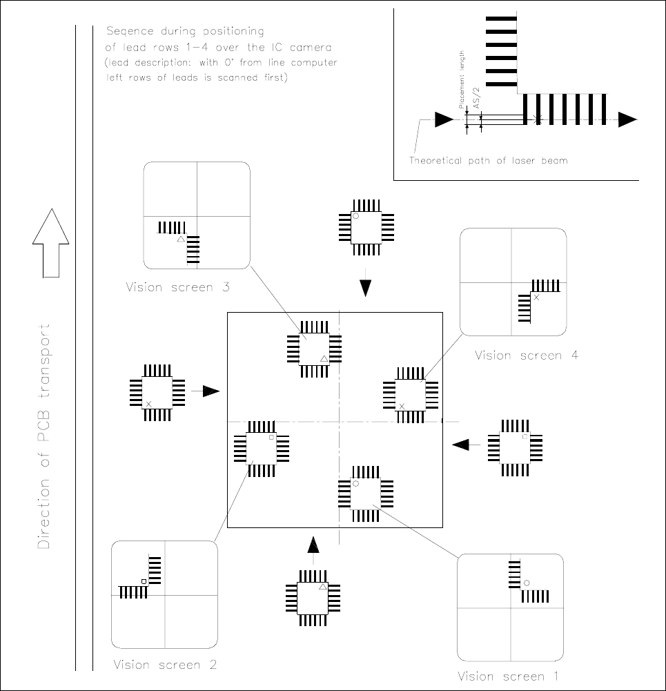
NOTE
The order in which lead rows are positioned over the IC camera as shown in Fig. 1.8.2
corresponds to the
order of positioning and/or scanning during the coplanarity measurement.
During the simulation of the measurement, the error message
"Measurement error! Coplanarity cannot
execute command" is reported -> you can ignore this message.
1 Retrofitting Instructions for Coplanarity Option SIPLACE 80 F4/(F4-6)/F5
1.8 Configuring the Option (at Line Computer and Station Computer) and Putting It into Service Edition 05/99
1 - 27
Fig. 1.8.2 Monitor Image, Order of Scanning of Lead Rows
● During the next cycle the measurement of the second row of leads is simulated. Now you can check the
position of the last lead in the row, as above.
-> Where components with long rows of lead or wide spaces between leads are involved, the start and
stop position may be located outside the camera´s field of view and it may therefore be impossible to dis-
play them on the screen.
● Conduct this test for all four sides (see Fig. 1.8.2).
● If the leads are not struck exactly during this process (see Fig. 1.8.2, “Presentation Top Right”) check the
GF description (see “Operating Manual for UNIX Line Computers”) and, where applicable, the calibration.
● Abort the placement and remove the PCB.
● Deactivate the clock mode, turn off the test functions and exit the menu.