80S20 circuit.pdf - 第51页
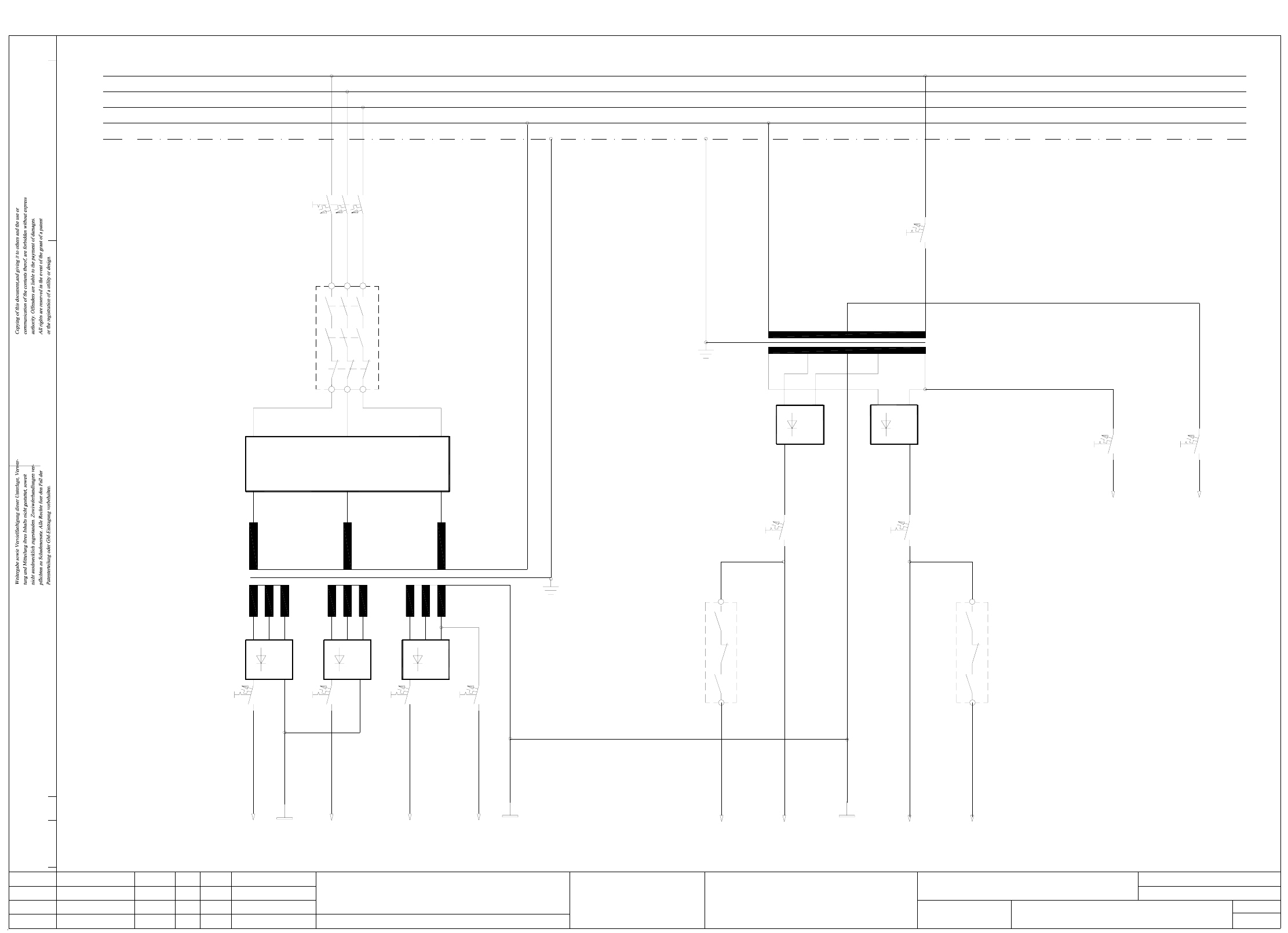
3 SIPLACE 80S-20 Circuit Diagrams 51 00321086-050101FD3 SIPLACE 80S20/F4 safety concept (power unit) (Sh. 1 of 3) 01. 01. 05. 23.01.98 Leh AUT 5 00321086-05 1L+ 1L- 3L+ 2L+ 23.01.98 Leh 23.01.98 Leh Tuth 21.07.98 12345 (…
3 SIPLACE 80S-20 Circuit Diagrams 50
00116900-020101FD3 Input/output assignment, SIPLACE 80S20 (Sh. 2 of 2)
SIEMENS
91011
'Request' to conveyor 2 from previous station
'Transferred' to conveyor 2 from previous station
'Received' to conveyor 2 from following station
'Permission' to conveyor 2 from following station
Bero, ceramic substrate centering, conveyor 2
Bero, lifting table top position, conveyor 2
Bero, lifting table bottom position, conveyor 2
Limit switch, width adjustment, conveyor 2
Bero, position width adjustment, conveyor 2
X5sg: 9
X5sg:11
X5sg:10
X5sg: 8
X5sg: 7
X5sg: 6
X5sg: 5
X5sg: 1-4(*)
A6/X5ki:15
A6/X6ki:5
A6/X6ki:7
A6/X6ki:6
A6/X5ki:14
+24VDC
A6/X5ki:18
A6/X5ki:19
A6/X5ki:P
X4sg: 9
X4sg:11
X4sg:13-14
X4sg:12
X4sg:10
X4sg: 8
X4sg: 7
X4sg: 6
X4sg: 5
GND
Port E6.4
Port E6.6
Port E6.5
Port E6.3
Port E6.2
Port E6.1
Port E6.0
Input
Port E5.4
Port E5.6
Port E5.7
Port E5.5
Port E5.2
Port E5.3
Port E5.1
Port E5.0
Input
18
00116900-020101FD3
12 13 14 15 16 17
Sh.
Sh.
Motor, output conveyor on slow 1, conveyor 2 Port A5.4X2sg: 9
Output
Valve, ceramic substrate centering, conveyor 2
Motor, width adjustment wider, conveyor 2
Motor, width adjustment narrower, conveyor 2
Motor, width adjustment fast, conveyor 2
'Permission' to previous station from conveyor 2
'Transferred' to following station from conveyor 2
'Request' to following station from conveyor 2
'Received' to previous station from conveyor 2
Motor, output conveyor on fast, conveyor 2
Motor, output conveyor on slow 2, conveyor 2
Motor, input conveyor on fast, conveyor 2
A6/X5ki:19X3sg: 7
X4sg: 1-4(*)
X3sg:12
X3sg:13-14
X3sg: 9
X3sg:10
X3sg:11
X3sg: 8
GND
+24VDC
A6/X5ki:M
A6/X5ki:8
A6/X5ki:5
A6/X5ki:7
A6/X5ki:6
A6/X5ki:18
X3sg: 5
X3sg: 6
X3sg: 1-4
X2sg:13-14
X2sg:12
X2sg:11
X2sg:10
+30VDC switched
A6/X5ki:15
A6/X5ki:14
A6/X5ki:G
GND
PCB handling
Port A6.2
Port A6.7
Port A6.6
Port A6.5
Port A6.4
Port A6.3
Output
Port A6.1
Port A6.0
Port A5.7
Port A5.6
Port A5.5
Extend lifting table, PCB clamping, conveyor 2
Retract lifting table, PCB release, conveyor 2
Motor, center conveyor on slow, conveyor 2
Motor, center conveyor on fast, conveyor 2
X2sg: 7
X2sg: 8
X2sg: 6
X2sg: 5
X2sg: 1-4
Plug desig.
board,
Conversion
+24VDC
Signal designationI/O terminal
Port A5.2
Port A5.3
Port A5.1
Port A5.0
Address
Conversion
board,
PCB handling
Function status
Product status
Doc. status
SMD Placement System Siplace 80S20
2
2Status DateModified Name Stand. Orig./Repl.f/Replaced by
CAD file:
Mat. no.:
Check.
Date
Author
Stromlaufplan/Circuit diagram
SIPLACE 80S20
Input/output assignment
1.
13.01.97
Wer
Pins marked with an '*' are not hard-wired !
1.
2.
13.01.97
13.01.97
1
X5sg:13-14
X5sg:12
14.08.1995
Wer
Wer
Haas
234
GND
A6/X5ki:M
A6/X6ki:8
116900F2
AUT 5
00116900
5678
Port E6.7
3 SIPLACE 80S-20 Circuit Diagrams 51
00321086-050101FD3 SIPLACE 80S20/F4 safety concept (power unit) (Sh. 1 of 3)
01.
01.
05.
23.01.98
Leh
AUT 5
00321086-05
1L+
1L-
3L+2L+
23.01.98
Leh
23.01.98
Leh
Tuth
21.07.98
12345
(x, y axes)
(star/lifting table)
(tape cutter)
4L+
2L-
67
(ext. WPC)
8
SIEMENS
910
switched
24VAC
(x, y slow)
V3
F4 F5 F6
V1 V2
F7
T2
00321086-050101FD3
7L+6L+
2L-
5L+
11 12 13
switched
14 15
(star slow)
(dp1/Z axes)
(Lifting table)
1816 17
K2
F9F8
control unit
To
150VAC
safety circuit
24VAC
To
F2
current limiter
Inrush
A1
K1
L1
L2
L3
PE
N
T1
V5
F10 F11
F3
PE
L3
N
L2
L1
V4
13
14
K2
23
24
Function status
Product status
Doc. status
SMD Placement System Siplace 80S20/F4
1
3Status Modified Orig./Creat. f./Creat.by
Date
Author
Check.
Stand.NameDate
Mat. no.:
CAD file:
Sh.
Sh.
00321086-050101FD3_SH1
Stromlaufplan/Circuit diagram
(power unit)
Safety concept
Circuit diagram overview
3 SIPLACE 80S-20 Circuit Diagrams 52
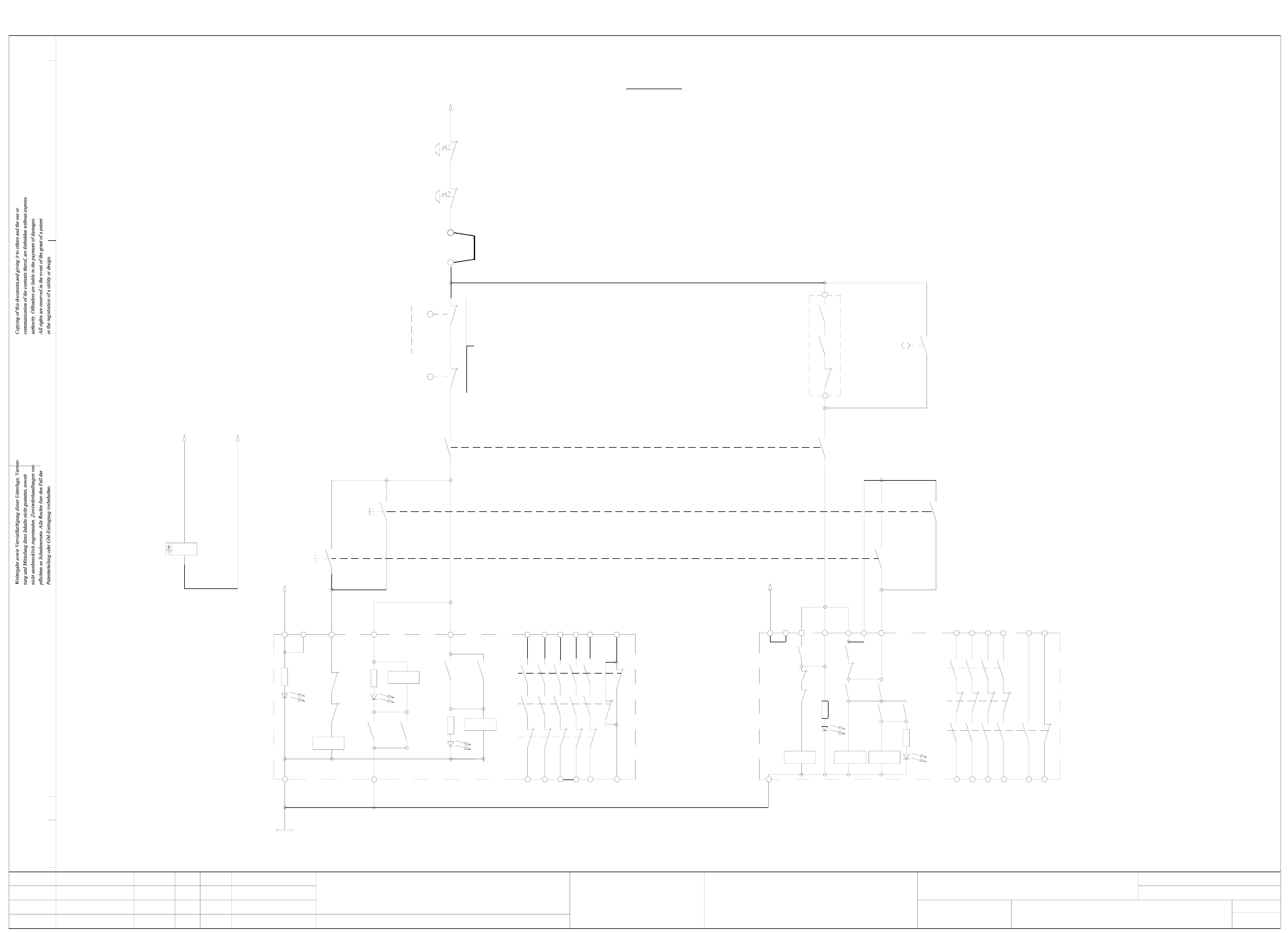
00321086-050101FD3 Siplace 80S20/F4 safety concept overview (safety circuit) (Sh. 2 of 3)
AUT 5
SIEMENS
Safety circuit
01.
01.
05.
44
43
54
53
Key-operated switch
00321029-S4
K1
6557433323
13
X6
24V AC
24
14 34 44
58 66
L2
K1' K2'
(ON button)
(output)
(input)
5343
3323
13
X5X3
24V AC
X6
L2
X1L1
Function status
Product status
Doc. status
SMD Placement System Siplace 80S20/F4
2
3
POWER SUPPLY
UNIT
Status Modified Date Name Stand.
Check.
Author
Date
Mat. no.:
CAD file:
Orig./Creat. f./Creat.by
Sh.
Sh.
00321086-050101FD3_SH2
Leh
23.01.98
H1: LED MAIN
Leh
Leh
23.01.98
23.01.98
1
21.07.98
Tuth
234
H2+H3 = release
00321086-05
56789
H2: LED channel 2H3: LED channel 1
3414
24
44
54
66
X4
K1 3TK2805-0AC2
K1'
K2'
H1
K3'
K2'K2'
K1' K3'
H2
H3
K1'
K2'
K3'
K1' K2'
K1
K3'
65
00321528-S2
00321029-S2
00321086-K3
Software release
for machine ON
00321086-K3
Cover switches
00303617-S1
(1-n)
00321416-S1
Connection for external
safety loops
X211
X211
00321528-S1
EMERG.-STOP button
EMERG.-STOP button
(input)
(output)
00321029-S1
~24VAC
Stromlaufplan/Circuit diagram
00321086-050101FD3
14
H1': LED release
Safety concept overview
(safety circuit)
10 11 12 13
H2': LED ready
H1'
15 16 17 18
K2 3TK2804-0AC2
K3'
K2'
H2'
K3'
K1' K3'
K1'
K2'
K1'
L1 X1
K1'
K1'
K2'
K3'
X5
K3'
X3X2 X4