00193732-02.pdf - 第50页
2 Retrofit Instructions for PCB Camera Multicolor, HS-50 / HS-60 SIPLACE HS- 50/HS-60 2.5 Preparatory Steps 11/2004 Edition 50 2.5 Prep aratory Step s : Open the s afety hoo ds. : Remove the r eject bin. : Disassemb le t…
SIPLACE HS-50/HS-60 2 Retrofit Instructions for PCB Camera Multicolor, HS-50 / HS-60
11/2004 Edition 2.4 Retrofit Kits, Tools
49
2.4 Retrofit Kits, Tools
2.4.1 Retrofit Kit "PCB Camera Multicolor HS-50 / HS-60"
2
2.4.2 Tools, Auxiliary Test Equipment and Expendable Materials
– Set of Allen wrenches
– Oblique-nosed cutting pliers
– Open-end wrench or size 6 mm socket wrench
– Wire stripper
– ESD bracelet
– Crimping pliers made by AMP (for connector sleeves)
– Insulating tape and permanent marker
– Ethyl alcohol.
1 Retrofit kit "PCB camera Multicolor HS 50 / HS-60" Item no: 00358031-01
4 PCB camera Multicolor assembly made by Sticksel each with 2 con-
nection cables
Item no: 00355462-01
4 Distance plate (= spacer) Item no: 00348078-01
12 hex head cap screw M3 x 14 (captive) Item no: 00327105-01
4 PC camera board, modular, made by Sticksel Item no: 00344490-01
12 Spacer bolts, PCB camera, L = 8.5 mm Item no: 03000189-01
4 Retrofit kit for PCB camera HS-50, main distribution frame consisting of: Item no: 00357512-01
1 Converter 24V/50V (universal illumination converter) Item no: 00349095-01
1 Relay RS 30 / 24 VDC GSE 1 A, Order no. 110166 Item no: 00345646-01
2
Feed-through terminal, gray, 3-wire Item no: 00336767-01
1
Closing plate 2.5 mm, orange, 3-wire Item no: 00336771-01
1
Transverse link (gray), 3-wire Item no: 00336773-01
1
End clip with no screws Item no: 00353373-01
1 cable W1, W2, W3, W4, W5
4 Twin connector sleeve, grey, 4 x 0,75 mm
2,
manufacturer: Bürklin
Order no: 18H 7081
4 Distance bolts (length: 5 mm, thread M3)
2 Retrofit Instructions for PCB Camera Multicolor, HS-50 / HS-60 SIPLACE HS-50/HS-60
2.5 Preparatory Steps 11/2004 Edition
50
2.5 Preparatory Steps
: Open the safety hoods.
: Remove the reject bin.
: Disassemble the head crash protections.
: Undock the movable component changeover tables.
: Turn the machine off at the main switch, isolate the machine from the mains, turn off the flow
of compressed air at the compressed air unit.
: Push the X-gantries toward the outside of the machine so that the placement heads are readily
accessible.
2.6 Changeover at Main Distribution Frame
: Open the machine frame door and the safety hood at feeder location 4, to the left of the input
station.
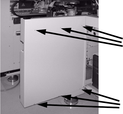
: Undo the 3 socket hex head cap screws on top of the side panel (just loosen the 3 screws on
the bottom).
: Lift the side panel of the machine frame straight up out of the slots.
: Set it on the side of the machine so that the main distribution frame is readily accessible.
Do not damage the grounding cable.
Undo screws
Loosen screws
SIPLACE HS-50/HS-60 2 Retrofit Instructions for PCB Camera Multicolor, HS-50 / HS-60
11/2004 Edition 2.6 Changeover at Main Distribution Frame
51
2.6.1 Disconnect the Wiring, Remove the PCBs
: For info, see also the circuit diagram Fig. 2.14.6 (= status before conversion).
: Before detaching the wiring, identify the wires in the main distributor as shown in the above
circuit diagram (flags 1 - 5).
: To do this, use insulating tape and water-resistant felt-tip pen.
: Use a slotted-head screwdriver, size 1, for the catch clamp connections X6dp and X1dq:
Detach the plug-in connectors of the identified wires (1 - 5) on the "Distributor illumination flash"
board.
: At X6dp GND, only detach the fixing for the zero wire that runs from X6dp GND to the 0 V bus-
bar (see Fig. 2.14.6).
: The zero wire detached at X6dp will be needed again (see cable W5 in Fig. 2.14.8).
: At X1dq Zero, only detach the fixing for the zero wire that runs to the 0 V busbar (see Fig.
2.14.6).
This zero wire will not be needed again, but is left in the cable duct.
2
2
2
2
2
2
2
2
2
2
2
2
2
2
2
2