00193732-02.pdf - 第62页
2 Retrofit Instructions for PCB Camera Multicolor, HS-50 / HS-60 SIPLACE HS- 50/HS-60 2.7 Installing PCB Camera Board and PCB Camera Multicolor 11/2004 Edition 62 Laying ca bles 2 : Run both ca bles, if possible, a s sho…
SIPLACE HS-50/HS-60 2 Retrofit Instructions for PCB Camera Multicolor, HS-50 / HS-60
11/2004 Edition 2.7 Installing PCB Camera Board and PCB Camera Multicolor
61
HS-50 and HS-60 2
: Put the PCB camera Multicolor, eventually with distance plate, in right position upwards onto
the distance plates.
: Screw the camera with the 3 unloosable Allan screws M 3 x 14.
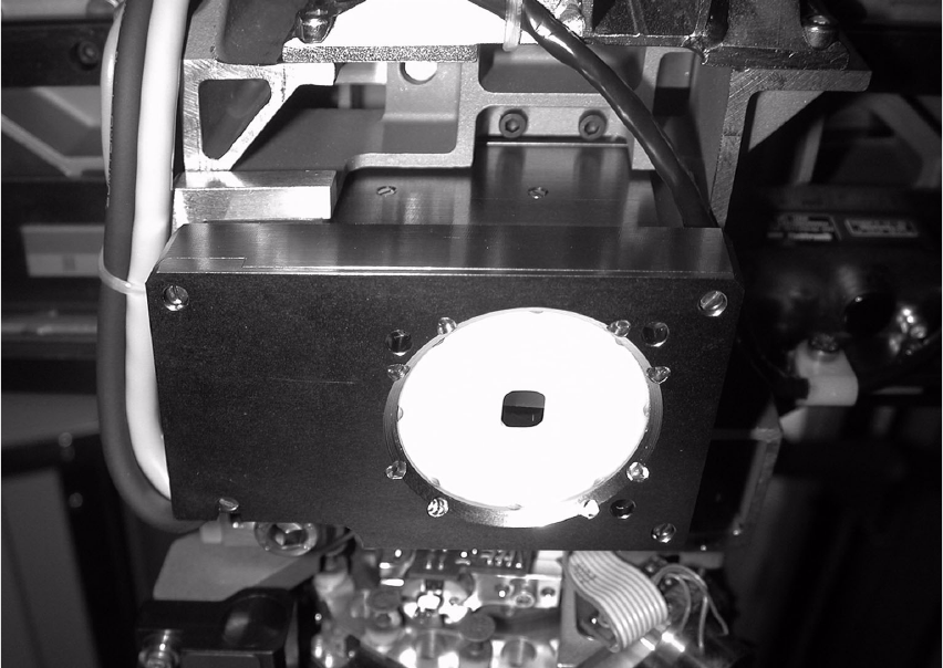
Abb. 2.7.4 Fastening the PCB Camera Multicolor (View from below, diagonally)
2
2
2
2
2
2
2
2
2
2
2
2 Retrofit Instructions for PCB Camera Multicolor, HS-50 / HS-60 SIPLACE HS-50/HS-60
2.7 Installing PCB Camera Board and PCB Camera Multicolor 11/2004 Edition
62
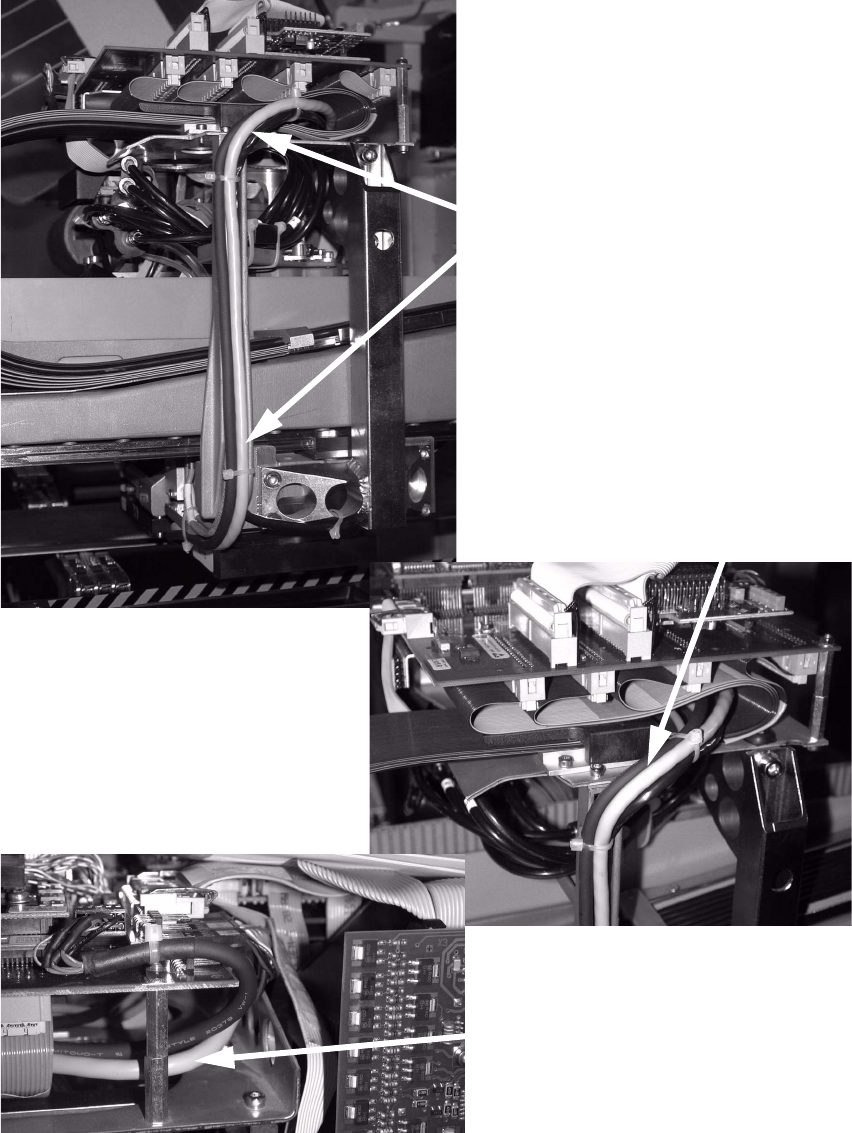
Laying cables 2
: Run both cables, if possible, as shown in the picture.
Mind a correct fixation of the cablesl.
2
Cable
Cable
Cable
SIPLACE HS-50/HS-60 2 Retrofit Instructions for PCB Camera Multicolor, HS-50 / HS-60
11/2004 Edition 2.7 Installing PCB Camera Board and PCB Camera Multicolor
63
2.7.3 Installing the "PCB Camera Board, Modular" from the Retrofit Kit
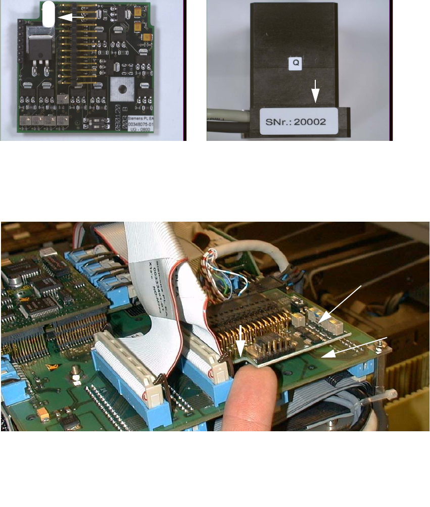
: Check the serial number of the PCB camera board, modular: It must correspond to the number
on the Multicolor PCB camera. Per gantry this allocation must be maintained during installa-
tion. The position of the number is shown in the following illustration.
Abb. 2.7.5 Check: the identical serial number on modular PCB Camera Board and PCB Camera Multicolor
: Screw the distance plates from the retrofit kit onto the "Vision board, modular".
: Plug the "PCB camera board, modular" onto the "Vision board, modular" in the correct position.
2
Abb. 2.7.6 Installing the "PCB Camera Board, Modular" from Retrofit Kit
: Screw the PCB camera board, modular.
1 Head PCB HS-50 assembly (modular)
2 PCB camera board, modular, manufacturer = Sticksel
3 Position of the recess
20002
3
2
1