wire-bonder.pdf - 第112页
WEST•BOND MODEL 454647E SERIES INSTRUCTION MANUAL 106 CLAMP ADJUSTMENT Tools required to setup the 45 ° Clamp Blade s: 1. Small Mirror (single surface mirro r preferred) 2. 0.028” Allen wrench 3. 5/64” Allen wrench 4. 3/…
WEST•BOND MODEL 454647E SERIES INSTRUCTION MANUAL
105
TOOL HEAD CONVERSION
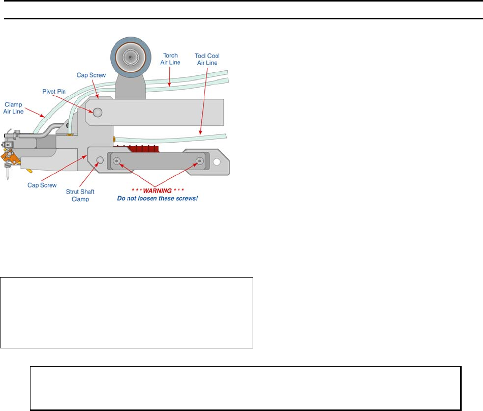
5) Bring the FORCE STRUT ARM up and slide
the STRUT SHAFT through the mounting hole
and clamp the shaft by tightening the Dutch
Key. Locate the air lines for the clamps and
the torch and connect them to their
respective hose barbs on the front panel.
Plug in each of the connectors (3 total) into
the sockets on the front panel. Finally,
change the machine model number as
described below.
Change Model Number of Machine
This option selects the model for the current tooling head installed.
Indicate Model Number of the machine:
->5=Model 4500E Wedge Bonder
6=Model 4600E Deep-Access Wedge Bonder
7=Model 4700E Ball Bonder A=ESC G=OK
ϑ To call “Model Selection”
From the H
OME menu press 8 (MORE OPTIONS) and then press 0 (MODEL SELECTION)
WEST•BOND MODEL 454647E SERIES INSTRUCTION MANUAL
106
CLAMP ADJUSTMENT
Tools required to setup the 45° Clamp Blades:
1. Small Mirror
(single surface mirror preferred)
2. 0.028” Allen wrench
3. 5/64” Allen wrench
4. 3/32” Allen wrench
5. Bond Tool
(0.750” Length)
6. Bonding wire
7. Work holder.
The following procedure is for setting the 45-
degree clamp blades. When adjusted properly
the clamps will feed the wire through the bond
tool straight, leaving the wire tail directly under
the bond foot for all subsequent bonds.
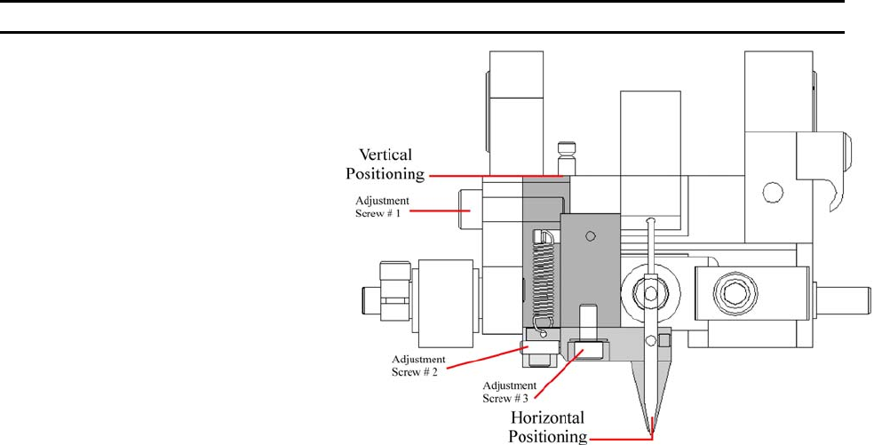
Vertical Positioning
1. Using the 3/32” Allen wrench, loosen Adjustment Screw #1.
2. Position the Clamp Assembly so that the top of the assembly and the top of the tooling body are
flush. Run finger over to feel for elevation differences.
3. Tighten Adjustment Screw #1.
4. Install Bonding tool and wire.
Horizontal Positioning
5. Using the 5/64” Allen wrench, loosen Adjustment Screw #3, and lightly tighten
6. Using the 0.028” Allen wrench, back Adjustment Screw #2 out. D
O NOT REMOVE!
7. Using the index finger of your right hand, push the lower clamp assembly to the left while holding
the entire head assembly with your left have.
8. Place the mirror on the workholder, under the clamp assembly. Focus the microscope so the back
of tool and clamps are visible in the mirror.
9. Using Adjustment Screw #2, Push the lower clamp assembly to the right until the wire from clamps
to bond tool is straight.
10. Tighten Adjustment Screw #3.
Testing
11. Keeping the work holder and mirror under the clamp assembly. Exit the EDIT Menu (ESC).
12. Looking through the microscope. Open and Close the clamps several times. Note any alignment
issues. (Repeat: Horizontal Positioning procedure if there is a problem).
13. Again, looking through the microscope, attempt several feed cycles, noting any alignment
problems.
WEST•BOND MODEL 454647E SERIES INSTRUCTION MANUAL
107
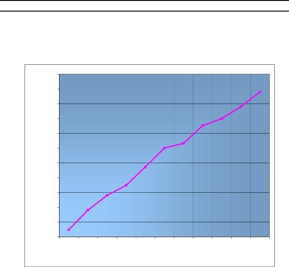
RADIANT HEATER CHARTS
Dial Settings for 0.750” Tools
This machine has been equipped with a Radiant Heater, which provides radiant heat around the bonding tool.
The heater temperature is adjusted by the multi-dial labeled T
OOL HEAT, located on the front panel.
Model 4546E
2½ Turn Heater at 0.750” Tool Length
12º
45º
87º
118º
150º
158º
188º
200º
220º
245º
70º
0
25
50
75
100
125
150
175
200
225
250
275
012345678910
DIAL SETTING
TEMPERATURE (DEGEES CENTIGRADE)