wire-bonder.pdf - 第26页
WEST•BOND MODEL 454647E SER IES INSTRUCTION MANUAL 20 MACHINE CONTROLS Front Panel C AM ER A B ACKLIGHT J AC K This jack is directly controlled by the Intensity Knob describe d above. LCD The Liquid Crystal Display is us…
WEST•BOND MODEL 454647E SERIES INSTRUCTION MANUAL
19
MACHINE CONTROLS
Front Panel
The 454647E Semi-Automatic Wire Bonder has been specifically designed to be versatile, dependable,
and easy to use. To effect this end, the following sections have been developed to help the operator take
advantage of its advanced bonding features. A in-depth study and understanding of this section will result
in better bonds, higher gram pulls, and faster set up times.
P
OWER SWITCH
Activates entire 454647E. Upon power-up, the microprocessor will complete several internal tests
and display a description of any problem detected. Refer to the Troubleshooting section (page
99) if an error is reported.
R
ESET SWITCH
When pressed, the machine re-homes all motor positions and returns the user to the home menu.
This button should be pressed once before the power is turned off. This prevents the tool head
from “snapping” back into the home position if it is down at search height when the power is
turned off.
T
OOL HEAT
See page 107 for dial settings and the corresponding temperature.
I
NTENSITY
This knob controls the available amount of camera backlighting. In bright (white surfaced)
packages this backlight is unnecessary and is difficult to even notice. However, in a dark or deep
package this option can greatly increase the visibility of the bonding pads.
WEST•BOND MODEL 454647E SERIES INSTRUCTION MANUAL
20
MACHINE CONTROLS
Front Panel
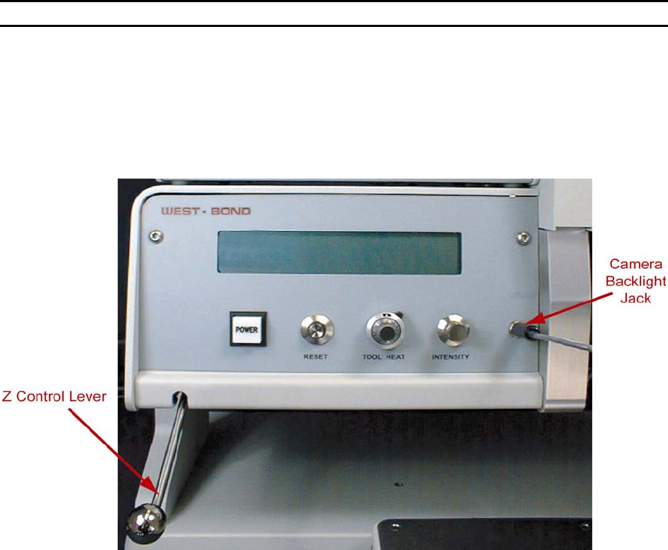
CAMERA BACKLIGHT JACK
This jack is directly controlled by the Intensity Knob described above.
LCD
The Liquid Crystal Display is used by the 454647E to communicate machine status, menu
prompts, explanations, and options. Four lines of text are available and each line is capable of
displaying 40 characters.
Z
CONTROL LEVER
Located at the far left on the machine front panel, this lever acts to bring the tool down to bond.
As with the manipulator arm, W
EST•BOND includes two Z-control levers (one high position style
and the other low position style).
G
O BUTTON (NOT SHOWN)
This is the small push-button switch located in the manipulator control ball. The Go button
controls two different features depending upon how it is used. When the button is quickly pressed
and released it operates the X-Axis braking system. This is done to aid the operator in scanning
the bond path along the Y-Axis. If this button is pressed and held, the bonder automatically goes
to Search before first bond. It pauses at search until the Go button is released. Once released,
the machine will complete the bonding sequence (if in Full-Auto mode). If the machine is set in
Half-Auto mode, it will pause before each operation, requiring a press of the Go button to
proceed.
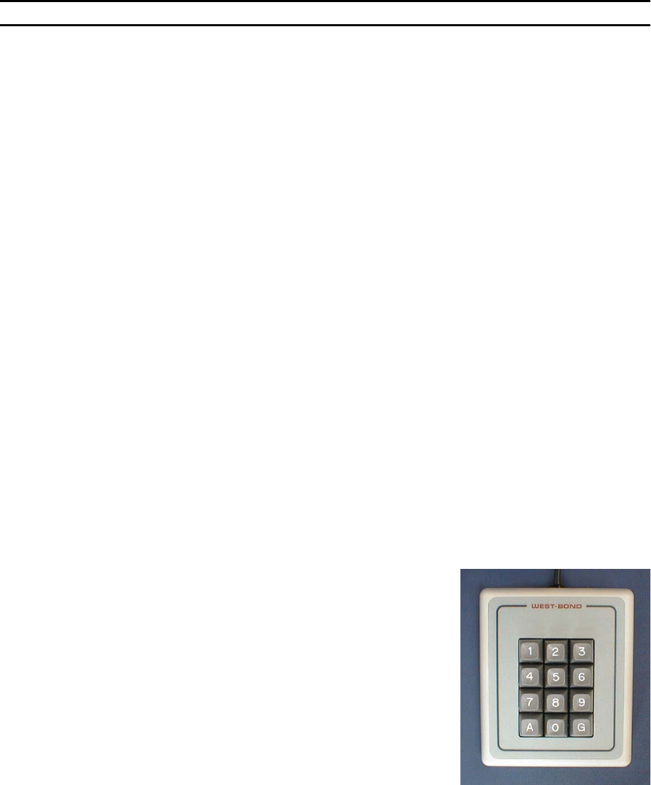
Key Pad
The KEY PAD, located on the left-hand side of the machine, enables the operator to access the
programmable and high level functions of the machine. Take extra time to read the LCD during
your first few programs for guidance to proper key strokes. Soon enough an operator will develop
time saving memorization of the menu’s and their location in the software. See the key format in
Programming section for more details (pages 40 to 87).
The following reserved keys will be used in most menus:
K
EY 1 = PREVIOUS MENU or ESCAPE - Press key “1” to escape
to the previous menu.
K
EY 2 = GO TO - Press key “2” for Go To options, such as: Go
To Device, or Go To Type.
K
EY 3 = HOME - Press key “3” to escape from any menu level,
or to return to the Align or “Home” Menu.
WEST•BOND MODEL 454647E SERIES INSTRUCTION MANUAL
21
MACHINE CONTROLS
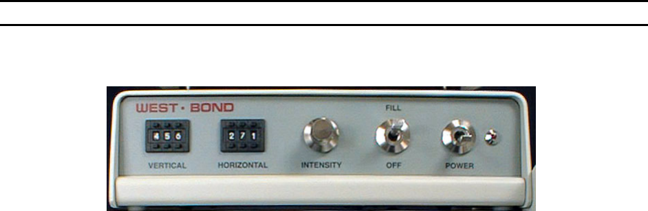
Crosshair Generator Controls
P
OWER
Activates the Crosshair Generator. Even if the crosshairs are not used, this unit must be turned
on for the video signal to be passed through to the monitor.
F
ILL
This switch turns the crosshairs on and off on the monitor.
I
NTENSITY
Controls the color and brightness of the crosshairs. When the Intensity knob is turned all the way
counter-clock wise, the crosshairs are bright white. When the knob is turned all the way clock
wise, the crosshairs will be black. Depending upon the package, the user may select between
these two colors to allow greater crosshair visibility.
H
ORIZONTAL CONTROL
This digital potentiometer controls the position of the horizontal crosshair. Increasing this number
lowers the position of this crosshair, while decreasing this number raises the crosshair on the
display screen.
V
ERTICAL CONTROL
This digital potentiometer controls the position of the vertical crosshair. Increasing this number
moves the position of this crosshair to the right, while decreasing this number moves the
crosshair on the display screen to the left.