ASM贴片机 X 系列机型电路图.pdf - 第206页
2 - 136 DPTH01 1_X2-03020 2 LD3 DP1-A c hse, T winHead, P&P-Modul 1, Port al 1, SIPLACE X2 (Bl. 1 v . 3) DP1 ax is, T winH ead, P&P modul e 1, gantr y 1, SIPL ACE X2 (s h. 1 of 3) Z1 te mper atur e se nsor Z1 cla…
2 - 135
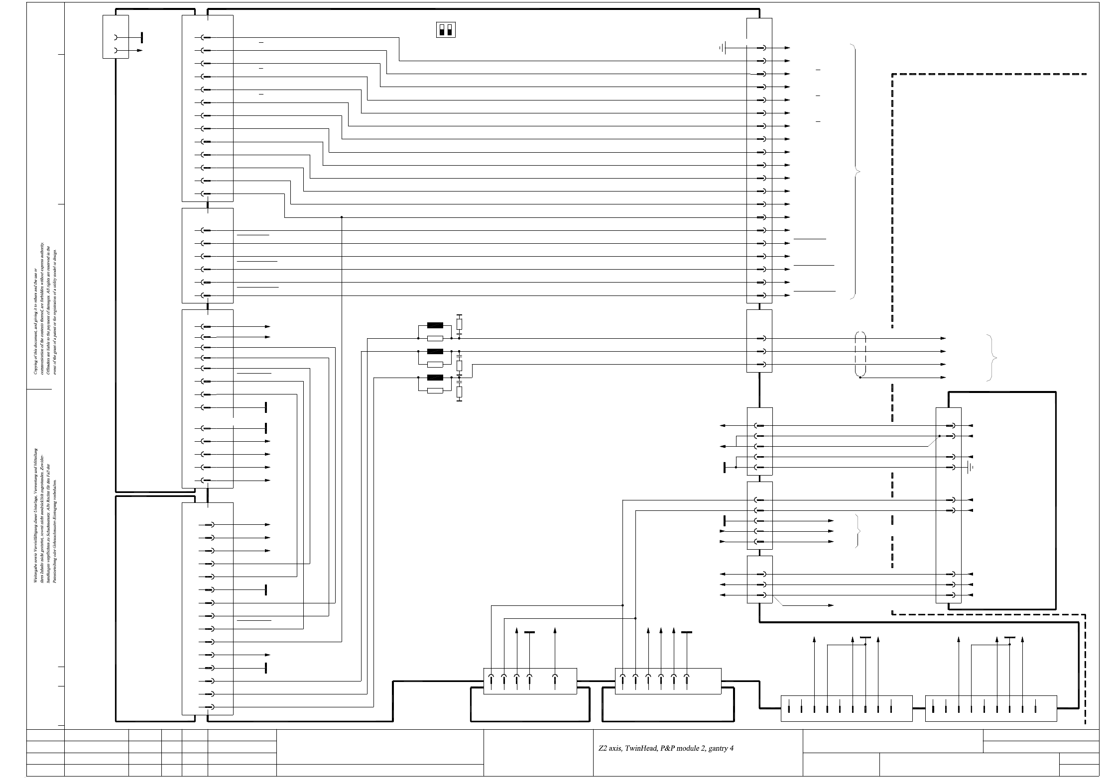
ZTH042_X3X4-010202LD3 Z2-Achse, TwinHead, P&P-Modul 2, Portal 4, SIPLACE X3/X4 (Bl. 3 v. 3)
Z2 axis, TwinHead, P&P module 2, gantry 4, SIPLACE X3/X4 (sh. 3 of 3)
Status
Function status
Revision status
Document status
Modified Date Name
Date
Author
Check.
Stand.
Mat.no.:
CAD file:
Orig./Repl.f./Repl.by
Sh.
Sh.(s)
09.03.08
04.03.09
17.02.11
09.03.2008TDH
TDH
TDH
TDH
ZTH042_X3X4-010202LD3_SH03.DWG
Copyright ©
ASM Assembly Systems
GmbH & Co. KG
Z2-Achse, TwinHead, P&P-Modul 2, Portal 4
SIPLACE X3/X4
SIPLACE X-Series
ZTH042_X3X4-010202LD3
3
3
DC/DC converter ±15V
Z4; D6
+15V
Backplane, axis unit
03048879 (tq)
A/C/E3,4,7,8,11
X07_2tq
B/D1,2,5,6,9-11
A/D22; B/E22,24,25; C20,25
03002141 (tq)
SDS60/3Z1 servo amplifier
A/C30
A/C32
C22; A/C24
C26; A/C28
C18; A/C20
C16
X1tq
C8
C14
C12
C10
A12
A8
C4
A4
A/C2
C23
C22
C12
B/E18
Phase_U
Phase_W
Phase_V
+150V_Star
I²t
PGND
00353450
Z20;D22
-15V
D30
Z28
Z8,16
D10,18
AGND
Servo_Ready
Servo_Enable
Inom_W
Inom_U
AGND
UB_Power_OK
-15V_Servo
+40V_Z/DP
+15V_Servo
+15V
-15V
+5V
+15V_Servo
AGND
GND
X22_2tq
X22_3tq
X22_3tq
A19
Axis card A364, gantry 3
A25
A16; B17
B16
A17
A24
X3tb
D16
D15
+15V
PGND
-15V
Vin(-)Axis
Vin(+)Axis
PGND
+40V_Z/DP
+150V_Star
(W3)
(W3)
(W3)
(W5)
(W5)
(W5)
BN
1
3
2
WH
GY
4
5
3
GN
WH
BN
(W1)
(W1)
(W2)
(W2)
(W1)
(W1)
(W1)
24
1
2
5
2
1
GNYE
1
3
2
1
4
3
Vin(+)_AXIS
SERVO_ENABLE
POWER_FAIL_AXIS
POWER_FAIL_24VDC
11
10
2
+40V_Z/DP
+150V_Star
Vin(-)_AXIS
GND_Z/DP
7
9
6
3
4
1
00354626
Power supply
WH+BN (W4)
C14, C18
B12, C17
+15V, EMERG_STOP_HEAD_AXIS
POWER_FAIL, X47sq:2
X45tq
X46tq
X47tq
03050920
X4ra:3
X4ra:2
X4ra:1
X4ra:1 Main distributor 03046226
Main distributor 03046226
X14
01.
02.
02.
03036027 (tb)
B16
E20
E21
B15
X2tb
C24
A18
C19
AGND
X4tb X3tb
C4
C1
A13
B19
A12
C13
B13
End signal
A14
B14
B15
A15
Z2 reference point
Inom_U
Servo_Ready
Servo_Enable
UB_Power_OK
Inom_W
Z2-Force-DATA
Z2-Force-DATA
Z2-Force-SCLK
Z2-Force-CS
Z2-Force-CS
Z2-Force-SCLK
Z2-Dir
I²t
Z2 clamping
R35
L16
L18
R36
R34
L17
Z2 track N
Z2 temperature sensor
OPTO_GND
+5V
Z2 track N
Z2 track B
Z2 track B
Z2 track A
Z2 track A
S1
ON
(S1.2 n.u.)21
OFF
1
DC/DC converter 5V/±15V
X51tq
D30
Z28
00353449
GND
-15V_Servo
+15V_Servo
D10
Z16;D18
D6
+5V
Z4,8,20
D22
X50tq
n.u.
n.u.
9
8
n.u.
n.u.
PA1_CAN_H
GND
PA1_CAN_L
Powerfail_24VDC 4
6
7
5
3
2
PA2_CAN_H
n.u.
n.u.
9
X30_1tq
7
8
6
GND
Powerfail_24VDC
PA2_CAN_L
n.u.
n.u.
4
5
3
2
1
X30_2tq
11
Phase_W
Phase_V
Phase_U
Z2-Force-SCLK
Z2-Force-DATA
Z2-Force-DATA
3
2
1
BN
GN
WH
X07_3tq
25
24
Z2-Force-SCLK
Z2-Force-CS
Z2-Force-CS
Z2 temperature sensor
Z2 clamping
Z2 reference point
19
22
21
18
16
n.u.
15
14
13
12
Z2-Dir
+5V
X23ca
Sheet 2
1,4,7,17,20,23,26
26-pole
PE
Act. value, S/Z2 axisX5vo/
Z2 track N
Z2 track N
Z2 track B
Z2 track B
Z2 track A
Z2 track A
9
10
8
6
OPTO_GND
2
5
3
X07_1tq 03009833
PE
Axis unit
Z2 motor_W
Screen
Z2 motor_V
Z2 motor_U
03050913
X13da
Sheet 2
03057572
Gantries 1 and 4
WH
GN
BN
BK
EMERG.-STOP_MAIN_AXIS
POWER_FAIL_24VDC
POWER_FAIL
2 - 136
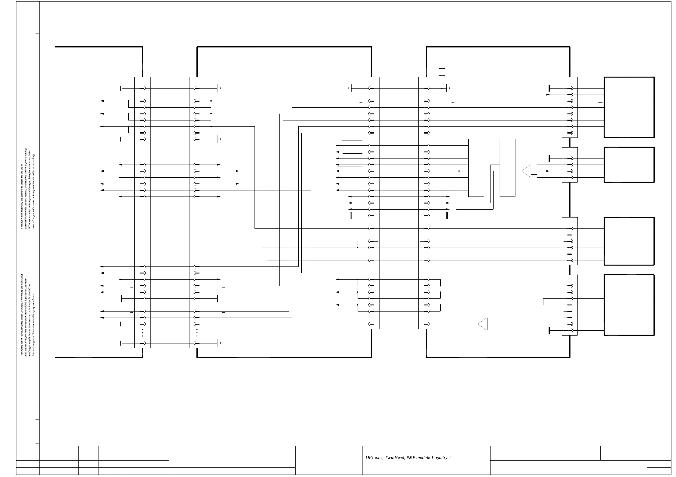
DPTH011_X2-030202LD3 DP1-Achse, TwinHead, P&P-Modul 1, Portal 1, SIPLACE X2 (Bl. 1 v. 3)
DP1 axis, TwinHead, P&P module 1, gantry 1, SIPLACE X2 (sh. 1 of 3)
Z1 temperature sensor
Z1 clamping
Z1 reference point
23
24
25
+15V
21
22
-15V
19 VCC
7
8 PE
DP1 motor U
DP1 motor V
DP1 motor W
4
5
6
3
X31bd:18
X5bd:4
X31bd:20
X31bd:21
X31bd:24
X31bd:23
X31bd:14
X31bd:15
X31bd:17
Twin flat ribbon cable loom
03004332-W1
1
X30bd
PE
00352833 (bd)
C600 head main board, P&P module 1
BN B+ (V)
P310.
4DP1 motor V22121
Z1 temperature sensor
Z1 motor W
Z1 motor U
Z1 motor V
DP1 motor V1
DP1 motor U
30 30
Z1 motor U 24
Z1 motor W
Z1 motor V
27
28
29
25
26
23
22
24
27
28
29
25
26
23
22
00353135
Key
GND
Key
7
8
6
BN
YE
Temperature sensor
A- (V)
A+ (U)
X17be
3
Key
4
5
1
2
BU
WH
GY
1
Key
2
3
GY
BU
Linear drive
Z1 axis
Linear motor
03014681
U-Sensor
TwinHead C700 force meas. board, P&P module 1
DP1 motor W
DP1 track B
DP1 track B
DP1 track A
DP1 track A
DP1 track N
DP1 track N
DP1 motor U
DP1 motor V
DP1 motor W
Z1 temperature sensor
Z1-Force-SCLK
Z1-Force-SCLK
Z1-Force-Dir
Z1-Force-Dir
Z1-Force-CS
Z1-Force-CS
Z1-Force-DATA
Z1-Force-DATA
50
33
34
32
31
30
26
27
29
28
PE
DP1 track A
+24V
GND
DP1 track A
DP1 track B
DP1 track B
DP1 track N
DP1 track N
DP1 track A
50 PE
34
33
n.u.
+24V28
DP1 track A
DP1 track B
DP1 track B
GND31
32
29
30
DP1 track N
DP1 track N
27
26
X31bd:7, 8
X31bd:5, 6
X31bd:3, 4
2
4
5
3
1
7
8
19
21
23
22
6
24
25
X30br
Z1 temperature sensor
Z1 reference point
Z1 clamping
+15V
-15V
VCC
PE
DP1 motor W
DP1 motor V
DP1 motor U
P&P head adapter
03000902 (br)
Sheet 2
PE
+15V 17
+5V
GND
20
19
18
-15V
14
16
15
13
12
+15V17
20
19
18
GND
+5V
14
16
15
-15V
13
12
DP1 track N
10
11
9
8
7
DP1 track B
DP1 track N
DP1 track B
DP1 track A
DP1 track A
5
6
4
2
3
10
11
9
8
7
5
6
4
2
3
2
1
2
6
7
1
-
+
3
9
10
14
15 J13 J12
Force sensor
DP unit control cable
03005289
X8bd
PE 1
X8be
1PE
00352809 (be)
C37
220n
+5V
+5V2
Force transducer
U-Sensor +
OUT -
B- (W)
X16be
Key
5
6 YE
4
3
DISC-Magnetic-Motor
03000100
OUT +
RI
RI
T1
T2
T2
T1
X15be
GND 1
2
8
6
7
5
3
4
03000046
Encoder
Pick&Place module
GND
X18be
GND 1
PE
U-Sensor -
2
03.
02.
02.
Status
Function status
Revision status
Document status
Modified Date Name
Date
Author
Check.
Stand.
Mat.no.:
CAD file:
Orig./Repl.f./Repl.by
Sh.
Sh.(s)
09.03.08
04.03.09
17.02.11
11.01.2005TDH
TDH
TDH
TDH
DPTH011_X2-030202LD3_SH01.DWG
Copyright ©
ASM Assembly Systems
GmbH & Co. KG
DP1-Achse, TwinHead, P&P-Modul 1, Portal 1
SIPLACE X2
SIPLACE X-Series
DPTH011_X2-030202LD3
1
3
2 - 137
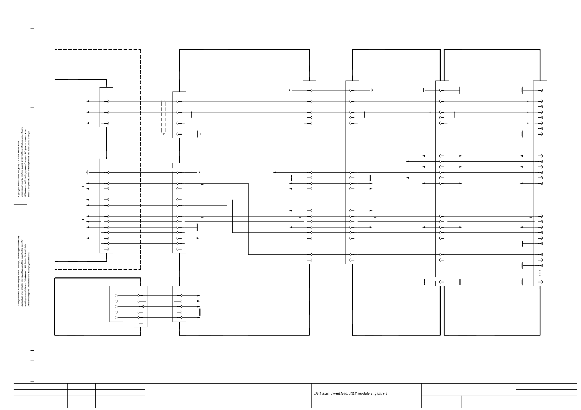
DPTH011_X2-030202LD3 DP1-Achse, TwinHead, P&P-Modul 1, Portal 1, SIPLACE X2 (Bl. 2 v. 3)
DP1 axis, TwinHead, P&P module 1, gantry 1, SIPLACE X2 (sh. 2 of 3)
DP1 motor U
DP1 motor V
DP1 motor W
DP1 track N
DP1 track N
DP1 track B
DP1 track B
DP1 track A
DP1 track A
Z1 clamping
VCC
+24V
+15V
GND
PE
DP1 track B
Sheet 3
X1qa
Main distributor
03046225 (qa)
-15V
+5V
0V
+15V
+24V
DP1 track N
DP1 track N
12+5V
n.u.
n.u.
14
13
n.u.
OPTO_GND
9
11
10
8
-15V
+15V
GND
+5V
+24V
Voltage
03009788
Cable carrier interface
2BN2(W1)BU
PK
Key
RD
WH
525(W2)
n.u.
66
GN
441
33
(W2)
(W1)
X6qa
OG WH1(W1)
2
5
4
3
1
X50ba
12 +5V
14
13
n.u.
n.u.
9
11
10
8
DP1 track N
n.u.
GND
DP1 track N
WH
1,4,7,17,20,23,26
Backplane
Axis unit
03048879 (sq)
DP1 track A
DP1 track A
DP1 track B
5
6
2
3
26-pole
Carrier cable 8, 1G
DP1/DP2 motor
3
4
5
2
1,10,14,34
X8ba
DP1 motor V3
DP1 motor W
5
4
DP1 motor U2
1,10,14,34
X8bc
PE
Z1 temperature sensor
Z1 reference point
+15V
X7bc:15
X7bc:14
88,90
60
+15V
-15V 87,89
81
68
VCC 83,85
-15V
VCC
102
100
104
106
X22bc/J3
PE 91,92
PE
Head interface
03000901 (bc)
Gantry 1
Z1 reference point
Z1 temperature sensor
24
25+15V
19
21
22
23
-15V
Z1 clamping
VCC
DP1 motor W
DP1 motor V
DP1 motor U
4
7
PE 8
6
5
X30br
3
2
PE 1
From sheet 1
P&P head adapter
03000902 (br)
140-pole34-pole34-pole
22-15V -15V22
03057572
03.
02.
02.
Status
Function status
Revision status
Document status
Modified Date Name
Date
Author
Check.
Stand.
Mat.no.:
CAD file:
Orig./Repl.f./Repl.by
Sh.
Sh.(s)
09.03.08
04.03.09
17.02.11
11.01.2005TDH
TDH
TDH
TDH
DPTH011_X2-030202LD3_SH02.DWG
Copyright ©
ASM Assembly Systems
GmbH & Co. KG
DP1-Achse, TwinHead, P&P-Modul 1, Portal 1
SIPLACE X2
SIPLACE X-Series
DPTH011_X2-030202LD3
2
3
PE
X3tp /
X09_1sq
Sheet 3
GN2Phase_V
Phase_W 3 BN
Phase_U
X09_3sq
1
Axis unit, gantries 1 and 3
03050896
03009795
Actual value
DP1 axis
5
6
2
3
DP1 track B
DP1 track B
DP1 track A
DP1 track A
1,4,7,17,20,23,26
X26ba
26-pole
PE
DP1 motor
Cable carrier interface
2DP1 motor VGN
BK
4
BN 3
PE
DP1 motor W
X16ba
WH
1DP1 motor U
X24ba:14
Gantry 1 or 3
Cable carrier interface
03010612 (ba)
30
32
33
27
28
29
25
26
DP1 track B30
DP1 track A
DP1 track A
32
33
DP1 track N
DP1 track N
DP1 track B
+24V
+15V
27
29
28
26
25
GND
7,13,134,140
GND
+24V
19
17
15
23
21
84,86
25
+24V
50PE
DP1 track B 30
31
32
34
33
DP1 track A
DP1 track A
PE
GND
28
29
27
26
DP1 track N
DP1 track B
+24V
DP1 track N
03038078
16,31
19
15
VCC
GND
19
16,31
Z1 clamping15