ASM贴片机 X 系列机型电路图.pdf - 第256页
3 - ii Wirksc haltp lanmappe S IPLACE X -Seri e / SIPLA CE X-Se ries Detailed Circuit Diagrams Folde r Ausg abe 02/201 1 DE/EN Edition
Wirkschaltplanmappe SIPLACE X-Serie / SIPLACE X-Series Detailed Circuit Diagrams Folder
Ausgabe 02/2011 DE/EN Edition
3 - i
3 Stromlaufpläne / Circuit diagrams
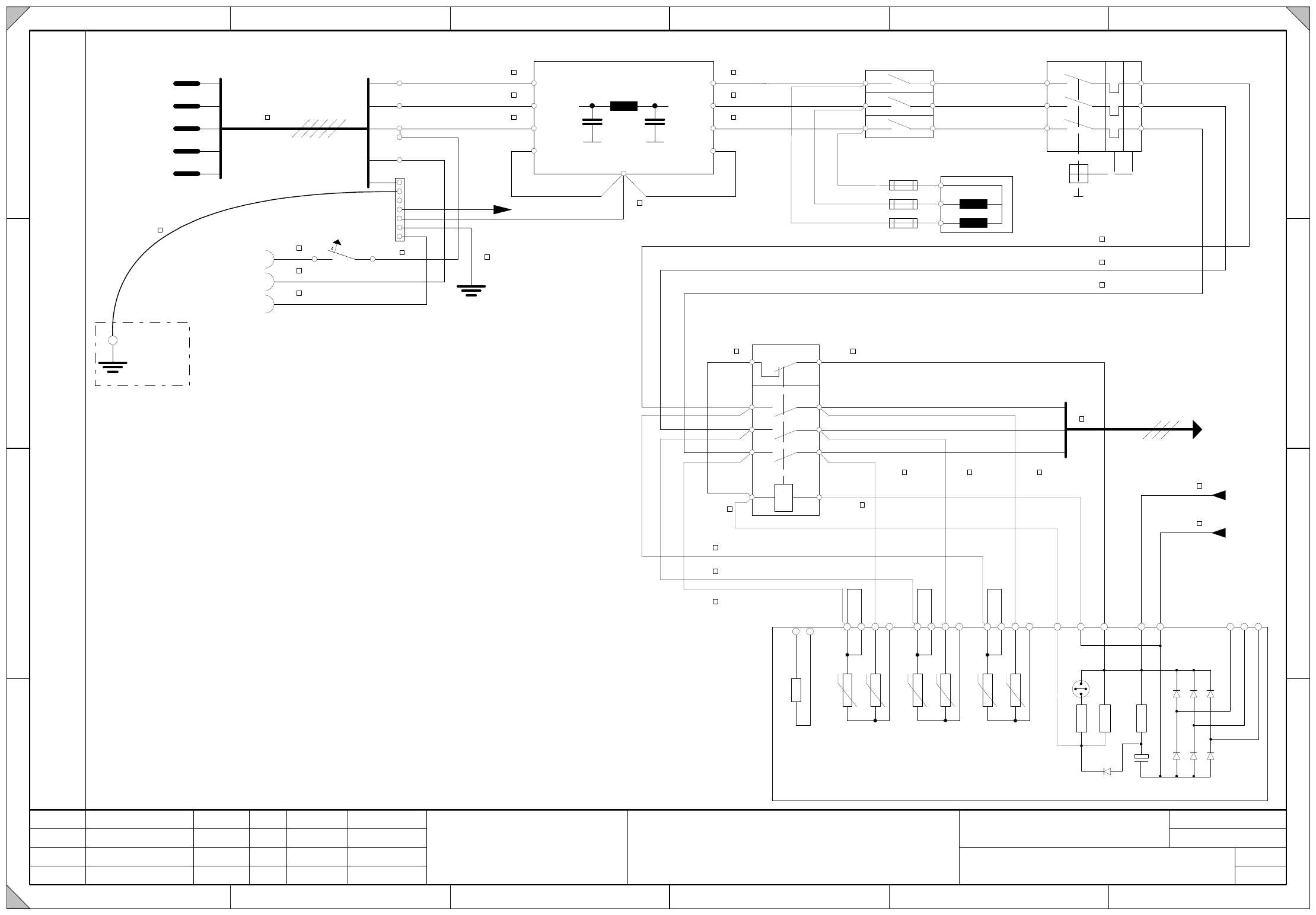
00354626-140301LD4 Stromversorgung (Bl. 1 v. 7)
Power supply (sh. 1 of 7) 3 - 1
00354626-140301LD4 Stromversorgung (Bl. 2 v. 7)
Power supply (sh. 2 of 7) 3 - 2
00354626-140301LD4 Stromversorgung (Bl. 3 v. 7)
Power supply (sh. 3 of 7) 3 - 3
00354626-140301LD4 Stromversorgung (Bl. 4 v. 7)
Power supply (sh. 4 of 7) 3 - 4
00354626-140301LD4 Stromversorgung (Bl. 5 v. 7)
Power supply (sh. 5 of 7) 3 - 5
00354626-140301LD4 Stromversorgung (Bl. 6 v. 7)
Power supply (sh. 6 of 7) 3 - 6
00354626-140301LD4 Stromversorgung (Bl. 7 v. 7)
Power supply (sh. 7 of 7) 3 - 7
03046225-010101LD3 Hauptverteiler (Bl. 1 v. 4)
Main distributor (sh. 1 of 4) 3 - 8
03046225-010101LD3 Hauptverteiler (Bl. 2 v. 4)
Main distributor (sh. 2 of 4) 3 - 9
03046225-010101LD3 Hauptverteiler (Bl. 3 v. 4)
Main distributor (sh. 3 of 4) 3 - 10
03046225-010101LD3 Hauptverteiler (Bl. 4 v. 4)
Main distributor (sh. 4 of 4) 3 - 11
03046226-010101LD3 Unterverteiler (Bl. 1 v. 4)
Sub-distributor (sh. 1 of 4) 3 - 12
03046226-010101LD3 Unterverteiler (Bl. 2 v. 4)
Sub-distributor (sh. 2 of 4) 3 - 13
03046226-010101LD3 Unterverteiler (Bl. 3 v. 4)
Sub-distributor (sh. 3 of 4) 3 - 14
03046226-010101LD3 Unterverteiler (Bl. 4 v. 4)
Sub-distributor (sh. 4 of 4) 3 - 15
03051894-010501LD4 Einschub Box-PC X-Serie
Unit Box-PC X series 3 - 16
03052698-010301LD4 Verteiler Spannungen Box-PC X-Serie
Distributor voltages Box-PC X series 3 - 17
03058133-010101LD3 Achseinschub A364 Verdrahtung - neu
A364 axis unit wiring - new 3 - 18
PE-010101LD3 Erdungskabel, Übersicht
Grounding cable, overview 3 - 19
3 - ii
Wirkschaltplanmappe SIPLACE X-Serie / SIPLACE X-Series Detailed Circuit Diagrams Folder
Ausgabe 02/2011 DE/EN Edition
3 - 1
3 Stromlaufpläne / Circuit diagrams
00354626-140301LD4 Stromversorgung (Bl. 1 v. 7)
Power supply (sh. 1 of 7)
Date
Drawn
Checked
StandardsNameModification
Sheet
of
21 6543
A
B
C
D
Date
Designer 9
21 6543
A4
Document-No. / Dokumentennummer:
Stat.
Item name / Benennung
W
e
it
e
r
g
a
b
e
s
o
w
ie
V
e
r
v
ie
lf
a
e
lt
ig
u
n
g
d
ie
s
e
r
U
n
t
e
r
la
g
e
,
V
e
r
w
e
r
t
u
n
g
u
n
d
M
it
t
e
ilu
n
g
ih
r
e
s
I
n
h
a
lt
s
n
ic
h
t
g
e
s
t
a
t
t
e
t
,
s
o
w
e
it
n
ic
h
t
a
u
s
d
r
u
e
c
k
lic
h
z
u
g
e
s
t
a
n
d
e
n
.
Z
u
w
id
e
r
h
a
n
d
lu
n
g
e
n
v
e
r
p
f
lic
h
t
e
n
z
u
S
c
h
a
d
e
n
e
r
s
a
t
z
.
A
ll
e
R
e
c
h
t
e
f
u
e
r
d
e
n
F
a
ll
d
e
r
P
a
t
e
n
t
e
r
t
e
ilu
n
g
o
d
e
r
G
e
b
r
a
u
c
h
m
u
s
t
e
r
-
E
in
t
r
a
g
u
n
g
v
o
r
b
e
h
a
lt
e
n
.
C
o
p
y
in
g
o
f
t
h
is
d
o
c
u
m
e
n
t
,
a
n
d
g
iv
in
g
it
t
o
o
t
h
e
r
s
a
n
d
t
h
e
u
s
e
o
r
c
o
m
m
u
n
ic
a
t
io
n
o
f
t
h
e
c
o
n
t
e
n
t
s
t
h
e
r
e
o
f
,
a
r
e
f
o
r
b
id
d
e
n
w
it
h
o
u
t
e
x
p
r
e
s
s
a
u
t
h
o
r
it
y
.
O
f
f
e
n
d
e
r
s
a
r
e
lia
b
le
t
o
t
h
e
p
a
y
m
e
n
t
o
f
d
a
m
a
g
e
s
.
A
ll
r
ig
h
t
s
a
r
e
r
e
s
e
r
v
e
d
in
t
h
e
e
v
e
n
t
o
f
t
h
e
g
r
a
n
t
o
f
a
p
a
t
e
n
t
o
r
t
h
e
r
e
g
is
t
r
a
t
io
n
o
f
a
u
t
ilit
y
m
o
d
e
l
o
r
d
e
s
ig
n
.
P
r
iv
ile
g
e
d
b
u
s
in
e
s
s
in
f
o
r
m
a
t
io
n
.
D
o
n
o
t
r
e
le
a
s
e
.
Copyright ©
ASM Assembly Systems
GmbH & Co. KG
21.05.2002
Tekin
FS14
404611
Tek
29.06.10
Stromversorgung
Power Supply
00354626-140301LD4
7
Schnedlitz W.
US04
404611
Tek
02.08.10
RS03
404762
Tek
11.11.10
X
1
-
1
4
X
1
-
1
3
X
1
-
1
2
X
1
-
1
1
L1
L2
L3
N
PE
PE
N
PE
F1
A1(+)
A2(-)
1
3
5
2
4
6
K1.1
2
SZ1(-)
I>
I>
I>
SZ1(+)
6A
4
2,5
2,5
2,5
6 br
6
6
6
6
1,5
1,5
4
6
6 br
6 br 6 br
6 br
6 br
6 br
1
6
X1
X102
0,75
0,750,75
0,75
0,75
X100
Z1
L1
L2
L3
L1
L2
L3
L1
L2
L3
L1'
L2'
L3'
T1
T2
T3
L1
L2
L3
T1
T2
T3
F1
L20
F23
3 xT6,3A
F22
F21
1
MPG MainGroundingPoint (frame)
RPG RackGroundingPoint
Frame
MGP
Three-phase power plug
Service socket
RGP
RGP
(Sheet 7)
Line filter
Main power switch Q1
Power switch Q2
main contactor K1
Contactor relay block (NC)
TransfPrim
(Sheet 2)
(Sheet 2/5)
(Sheet 2)
Inrush current limiter
transformer
R1-R6 = PTC Typ J201 20 Ohm
R
9
6
8
R
470uF/63V
R
8
6
8
R
R
7
4
7
R
D1
+
-
C1
D2 D4 D6
D3 D5 D7
D1-D7 =1N4007
S1
1 (off)
on
Hinweis!
Schalter S1 in Stellung "on".
R
2
R
4
R
6
R
3
R
1
R
5
R
1
0
0,75
X
5
-
4
1
X
5
-
4
2
X
5
-
4
3
X
5
-
4
4
X
5
-
4
5
X
6
-
1
X
6
-
2
X
6
-
3
1,51,5
1,5
1,5
X
3
-
3
4
X
3
-
3
3
X
3
-
3
2
X
3
-
3
1
X
2
-
2
4
X
2
-
2
3
X
2
-
2
2
X
2
-
2
1
X
4
-
4
7
X
4
-
4
6