00194440-10_SM_X-Series_Customer_en.pdf - 第35页
Overview of the Modules 2.2.5 Main Distributor Electrical System Service Manual SIPLACE X Series 35 2.2.5.2 2 . 2 . 5 . 2 M a in d is t r ib u t o r ( X s e r ie s f r o m M a . N o . B 3 2 6 ) Main distributor (X series…
Overview of the Modules
Electrical System 2.2.4 Power Supply [00354626-xx]
34 Service Manual SIPLACE X Series
2.2.4
2.2.4 Power Supply [00354626-xx]
Power Supply [00354626-xx]
Overview
2.2.5
2.2.5 Main Distributor
Main Distributor
Signals and voltages can be processed and transmitted to the different system assemblies via the main
distribution unit in sector 2.
2.2.5.1
2.2.5.1 Main distributor (X series up to Ma. No. B325)
Main distributor (X series up to Ma. No. B325)
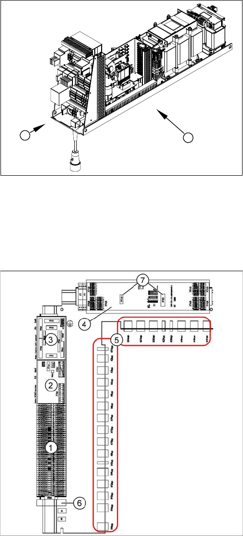
1. Front view
2. Side view.
The power supply unit is mounted on a compact rack unit
and is located in the left-hand middle section of the ma-
chine. A lockable door prevents access to the power sup-
ply.
1
2
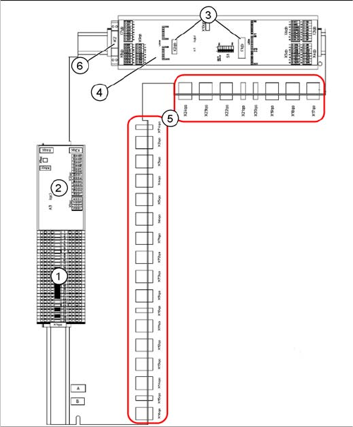
Main distributor (X-Series up to machine number B325)
[03010004-xx]
1. Terminal strip X1qa (GND, +5 V, +15 V, -15 V,
+24 V, various signals)
2. DC/DC converter for illumination of all cameras
(PCB, component and stationary cameras) in place-
ment area 2
3. Control board for illumination, Vision system for sta-
tionary cameras of TwinHead (A4)
4. CAN-Bus I/O module (A1)
5. Connector block (connection X2qa - X6qa, X71qa -
X74qa and X9qa - X24qa)
6. 8-fold AND connection for safety circuit (A5)
7. Socket for Interface 1-Wire CAT5
Overview of the Modules
2.2.5 Main Distributor Electrical System
Service Manual SIPLACE X Series 35
2.2.5.2
2.2.5.2 Main distributor (X series from Ma. No. B326)
Main distributor (X series from Ma. No. B326)
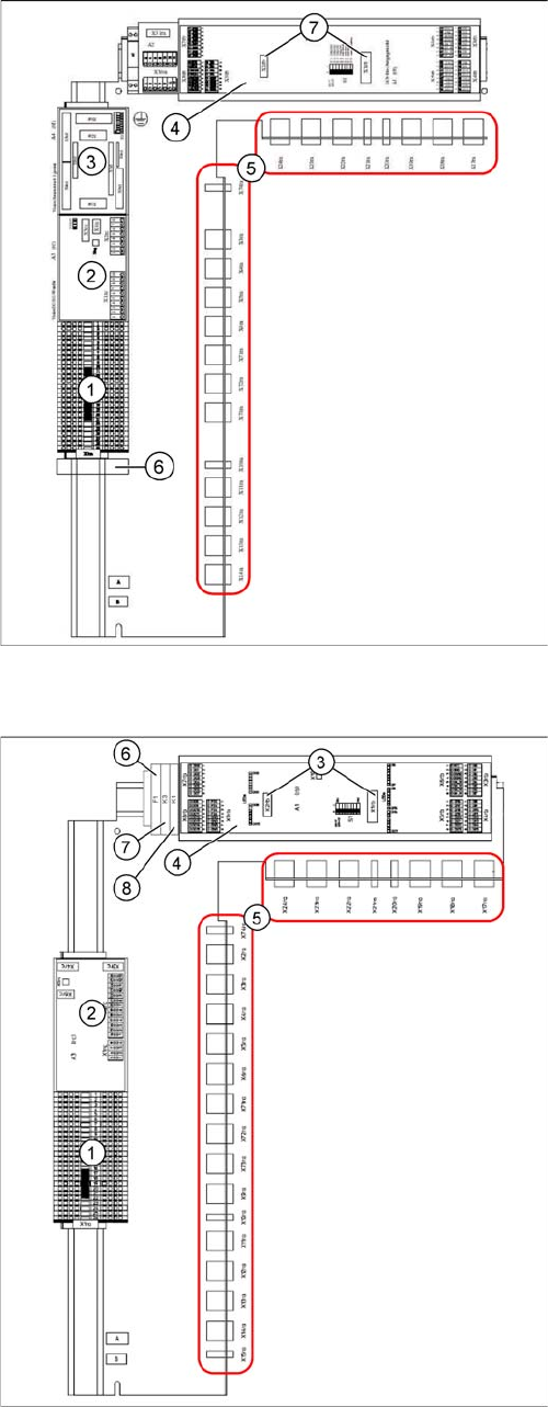
Main distributor (X-Series from machine number B326,
X4I) [03046225-xx]
1. Terminal strip X1qa (GND, +5 V, +15 V, -15 V,
+24 V, various signals)
2. DC/DC converter for illumination of all cameras
(PCB, component and stationary cameras) in place-
ment area 2
3. Socket for Interface 1-Wire CAT5
4. CAN-Bus I/O module (A1)
5. Connector block (connection X2qa - X6qa, X71qa -
X74qa and X9qa - X24qa)
6. Relay K2 switches the compressed air supply for the
placement heads off (can be configured in the station
software)
Overview of the Modules
Electrical System 2.2.6 Subdistributor
36 Service Manual SIPLACE X Series
2.2.6
2.2.6 Subdistributor
Subdistributor
Signals and voltages can be processed and transmitted to the different system assemblies via the sub-
distributor in sector 4.
2.2.6.1
2.2.6.1 Subdistributor (X series up to Ma. No. B325)
Subdistributor (X series up to Ma. No. B325)
2.2.6.2
2.2.6.2 Subdistributor (X Series from Ma. No. B326)
Subdistributor (X Series from Ma. No. B326)
Subdistributor [03010005-xx]
(X-Series up to machine number B325)
1. Terminal strip X1ra (GND,+5 V,+15 V,-
15 V,+24 V,+52 V, various signals)
2. DC/DC distributor for illumination of all cameras
(PCB, component and stationary cameras) in place-
ment area 2
3. Control board for Vision system illumination of sta-
tionary cameras, placement area 1 (future use) (A4)
4. CAN I/O module (A1)
5. Connector block (connection X3ra - X6ra, X71ra-
X74ra, X10ra - X24ra)
6. 8-fold AND connection for safety circuit (A5)
7. Socket for Interface 1-Wire CAT5
Subdistributor [03046226-xx]
(X-Series from machine number B326, X4I)
1. Terminal strip X1ra (GND,+5 V,+15 V,-
15 V,+24 V,+52 V, various signals)
2. DC/DC distributor for illumination of all cameras
(PCB, component and stationary cameras) in place-
ment area 1
3. Socket for Interface 1-Wire CAT5
4. CAN I/O module (A1)
5. Connector block (connection X3ra - X6ra, X71ra-
X74ra, X10ra - X24ra)
6. F1: Fuse for the cover fan
7. K3: Relay for cover fan
8. K1: This relay switches the main valve in the pneu-
matic unit.