00194610-01.pdf - 第26页
Retrofit instructions: Modification of the nozzle changer power supply for the DLM placement heads, HF series 07/2005 Edition 26 : Remove the side panels fr om the main an d sub-distributors (locat ions 2 and 4). 2 : Rem…
Retrofit instructions: Modification of the nozzle changer power supply for the DLM placement heads, HF series
07/2005 Edition
25
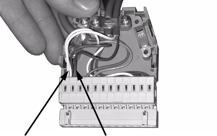
: Attach the new cable to the connector:
additional white at pin 1,
brown at pin 2.
2
2
: Tighten the screws of the strain relief.
: Fit the cover onto the connector.
: Connect the connector to its counterpart and pack the two connectors into the machine frame.
2
: Carry out this conversion at all the locations at which a C&P placement head with nozzle
changer is installed.
2
2
2
2
2
2
white at pin 1 (additional)
brown at pin 2
Retrofit instructions: Modification of the nozzle changer power supply for the DLM placement heads, HF series
07/2005 Edition
26
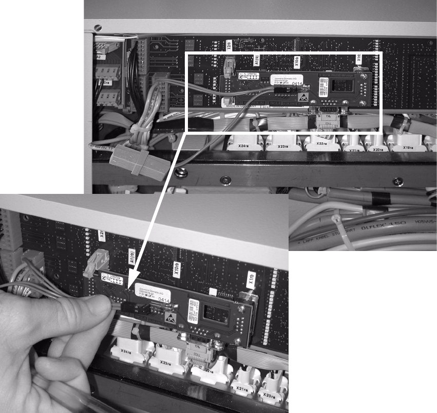
: Remove the side panels from the main and sub-distributors (locations 2 and 4).
2
: Remove the black 4-pin connector.
2
2
2
2
2
2
2
2
Retrofit instructions: Modification of the nozzle changer power supply for the DLM placement heads, HF series
07/2005 Edition
27
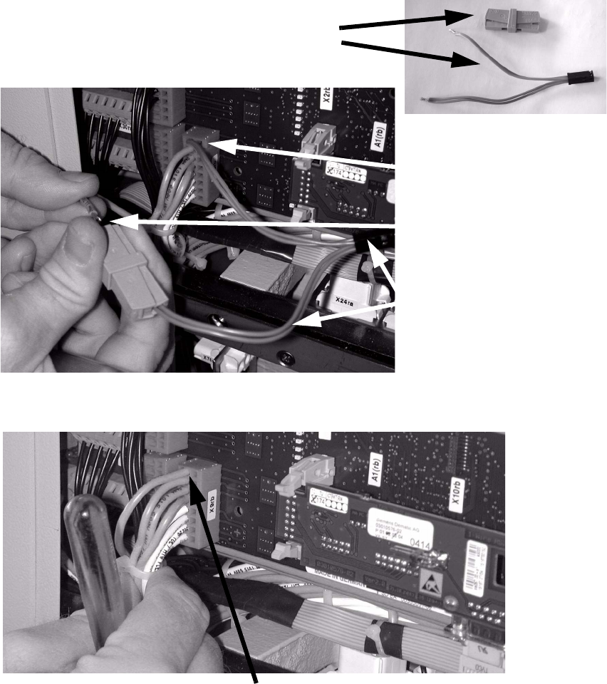
: Remove the unplugged cable together with the black connector and gray Wago terminal (see
photographs):
Remove the disconnected wire together with the Wago terminal.
Unplug the other end of the cable from terminal X9P24 (top connection).
2
: Connect the individual remaining cable to terminal X9P24 (top terminal).
2
: Reverse the cables on the main (location 2) and sub-distributors (location 4).
: Fit the two side panels.
Unplug Wago terminal
from connection
Cable and connector must be removed
Remove cable and connector
Unplug cable here
terminal X9P24, 24V
Attach loose cable at terminal X9P24