00191474-02.pdf - 第16页
Kabelhalterblech an der Kopfplatine Nachrüstanleitung HS-50 Ausgabe 11/99 16 ACHTUNG 7 Kontrol lieren Sie vor dem Au fsetzen d er Kopfp rozessorpl atine, daß 7 - keine S t ifte auf der Kopfpla tine (Po s. 2 in Abb. 7 - 1…
Nachrüstanleitung HS-50 Kabelhalterblech an der Kopfplatine
Ausgabe 11/99
15
7
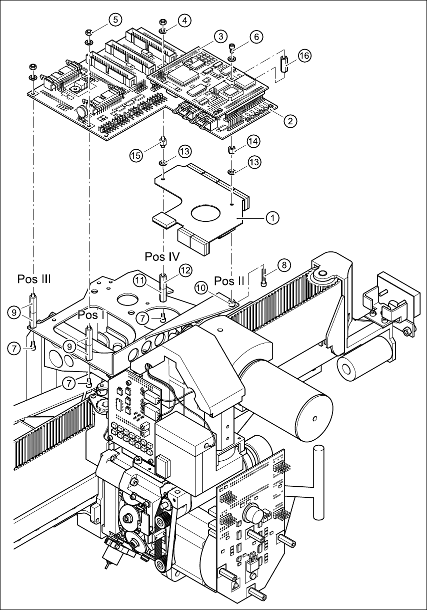
Abb. 7 - 1 Befestigungsteile und Kabelhalterblech montieren
Kabelhalterblech an der Kopfplatine Nachrüstanleitung HS-50
Ausgabe 11/99
16
ACHTUNG 7
Kontrollieren Sie vor dem Aufsetzen der Kopfprozessorplatine, daß 7
- keine Stifte auf der Kopfplatine (Pos. 2 in Abb. 7 - 1) verbogen sind.
- die Stecker der Kopfprozessorplatine auf den Stiftreihen der Kopfplatine exakt sitzen. 7
Å Drücken Sie vorsichtig die Kopfprozessorplatine gegen die Kopfplatine, bis die Stecker der
Kopfprozessorplatine auf der Kopfplatine aufsitzen.
Å Befestigen Sie die Kopfprozessorplatine an den Positionen I/III und IV mit den M3-Scheiben
(Pos. 4) und M3-Muttern (Pos. 5).
Å Befestigen Sie die Kopfprozessorplatine an Position II mit der Scheibe M3 (Pos. 4) und der Zy-
linderschraube M3x5 (Pos. 6).
Å Sichern Sie alle Schrauben und Muttern mit Loctite 243.
Å Stecken Sie die abgezogenen Kabelstecker wieder an.
Å Ziehen Sie der Reihe nach das Schutzpapier von den Kleberbändern ab (Pos. 2, 3, 5 und 6 in
Abb. 1 - 1) und drücken Sie die Flachbandkabel gegen die Klebebänder.
VORSICHT 7
Drücken Sie das Flachbandkabel nur leicht mit dem Zeigefinger gegen die Klebeflächen.
Anderenfalls riskieren Sie Kabelbrüche und damit Fehlfunktionen des Revolverkopfes. 7
Å Schnappen Sie das schwarze dp-Motorkabel am Rundkabelhalter (Pos. 4 in Abb. 1 - 1) ein.
8 Funktionstest
Å Entfernen Sie Werkzeug und sonstige Teile aus dem Automaten.
Å Schließen Sie die Schutzhauben.
Å Starten Sie den Automaten und beobachten Sie den Referenzlauf.
Retrofit instructions HS -50 Cable mounting plate on the head board
11/99 edition
17
1Overview
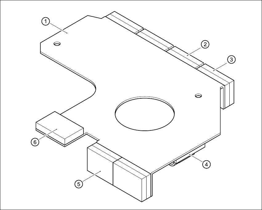
This manual describes how to retrofit the cable mounting plate (item 1 in Fig.1 - 1) and the
additional Velcro fasteners on HS-50 placement systems. 1
The cable mounting plate and Velcro fasteners are used to fix the cables for the DLM1 head. 1
1
Fig. 1 - 1 HS-50 cable mounting plate
Key to Fig. 1-1
(1) Cable mounting plate
(2) Velcro fastener for the vacuum board ribbon cable
(3) Velcro fastener for the ribbon cable of the incremental encoder for the turning station/DLM1
(4) Round cable holder for the motor cables of the turning station/DLM1
(5) Velcro fastener for the ribbon cable of the ‘Pick up’ positioning unit
(6) Velcro fastener for the ribbon cable of the ‘Discard’ positioning unit