00191474-02.pdf - 第17页
Retrofit instructions HS -50 Cable mounting plate on the head board 1 1/99 edition 17 1O v e r v i e w This manu al descr ibes how to retrofit the cabl e mounting plate (item 1 in Fig.1 - 1 ) and the additiona l V e lcro…

Kabelhalterblech an der Kopfplatine Nachrüstanleitung HS-50
Ausgabe 11/99
16
ACHTUNG 7
Kontrollieren Sie vor dem Aufsetzen der Kopfprozessorplatine, daß 7
- keine Stifte auf der Kopfplatine (Pos. 2 in Abb. 7 - 1) verbogen sind.
- die Stecker der Kopfprozessorplatine auf den Stiftreihen der Kopfplatine exakt sitzen. 7
Å Drücken Sie vorsichtig die Kopfprozessorplatine gegen die Kopfplatine, bis die Stecker der
Kopfprozessorplatine auf der Kopfplatine aufsitzen.
Å Befestigen Sie die Kopfprozessorplatine an den Positionen I/III und IV mit den M3-Scheiben
(Pos. 4) und M3-Muttern (Pos. 5).
Å Befestigen Sie die Kopfprozessorplatine an Position II mit der Scheibe M3 (Pos. 4) und der Zy-
linderschraube M3x5 (Pos. 6).
Å Sichern Sie alle Schrauben und Muttern mit Loctite 243.
Å Stecken Sie die abgezogenen Kabelstecker wieder an.
Å Ziehen Sie der Reihe nach das Schutzpapier von den Kleberbändern ab (Pos. 2, 3, 5 und 6 in
Abb. 1 - 1) und drücken Sie die Flachbandkabel gegen die Klebebänder.
VORSICHT 7
Drücken Sie das Flachbandkabel nur leicht mit dem Zeigefinger gegen die Klebeflächen.
Anderenfalls riskieren Sie Kabelbrüche und damit Fehlfunktionen des Revolverkopfes. 7
Å Schnappen Sie das schwarze dp-Motorkabel am Rundkabelhalter (Pos. 4 in Abb. 1 - 1) ein.
8 Funktionstest
Å Entfernen Sie Werkzeug und sonstige Teile aus dem Automaten.
Å Schließen Sie die Schutzhauben.
Å Starten Sie den Automaten und beobachten Sie den Referenzlauf.
Retrofit instructions HS -50 Cable mounting plate on the head board
11/99 edition
17
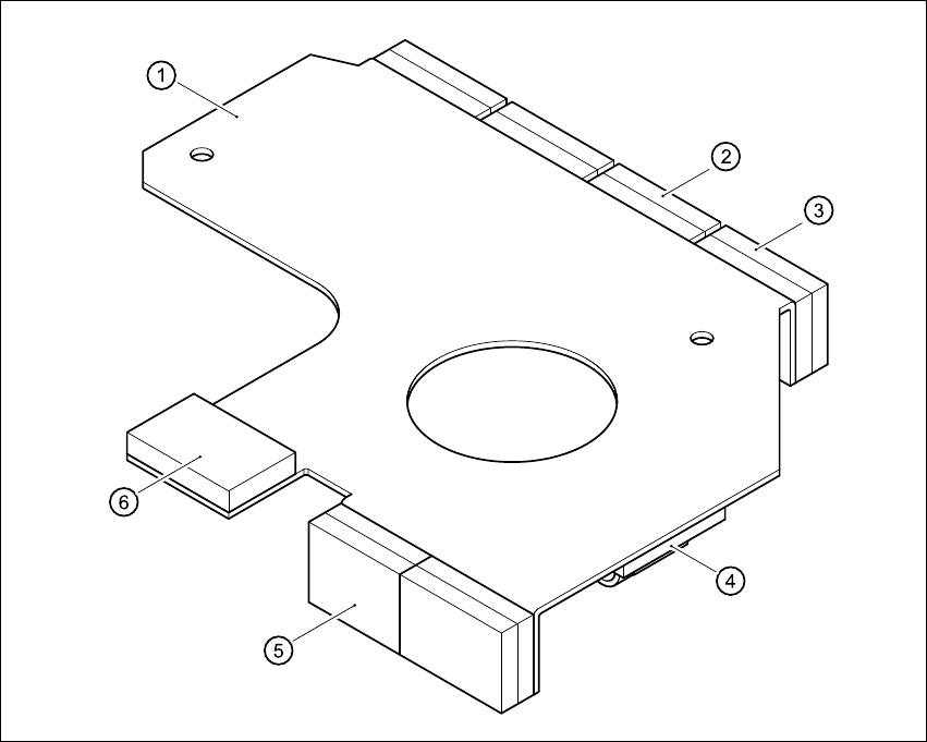
1Overview
This manual describes how to retrofit the cable mounting plate (item 1 in Fig.1 - 1) and the
additional Velcro fasteners on HS-50 placement systems. 1
The cable mounting plate and Velcro fasteners are used to fix the cables for the DLM1 head. 1
1
Fig. 1 - 1 HS-50 cable mounting plate
Key to Fig. 1-1
(1) Cable mounting plate
(2) Velcro fastener for the vacuum board ribbon cable
(3) Velcro fastener for the ribbon cable of the incremental encoder for the turning station/DLM1
(4) Round cable holder for the motor cables of the turning station/DLM1
(5) Velcro fastener for the ribbon cable of the ‘Pick up’ positioning unit
(6) Velcro fastener for the ribbon cable of the ‘Discard’ positioning unit
Cable mounting plate on the head board Retrofit instructions HS -50
11/99 edition
18
2 Safety instructions
WARNING
This retrofit must only be carried out by SIEMENS engineers. 2
Å Always follow the accident prevention regulations applicable in your country, e.g. EN 60204.
2
Å End all placement operations on the placement system.
Å Shut down the Windows NT operating system correctly, otherwise problems may occur when
restarting the placement system or data may be lost.
Å Switch the placement system off at the main switch.
Å Disconnect the placement system from the mains power supply.
Å Secure the system to prevent reclosing and put up a sign to indicate that servicing work is
being carried out (see section 2 – Operational safety of the operating instructions).
Å Open the protective covers and move the main gantry into a comfortable working position.
WARNING
To avoid damaging the revolver head, always observe the following points when moving the
gantry. 2
– NEVER move the gantry by pushing against the revolver head with your hands.
– NEVER move the gantry by pushing against the revolver head handle with your hands or by
pulling the handle. The revolver head may lose its settings or be damaged on account of the
high braking force of the y gantry drive.
– NEVER move the gantry while the z axis is lowered.
– Take hold of the cast iron part of the x axis and then move the gantry.
2