00192211-02_RI_ObliqueLighting.pdf - 第20页
Retrofit Instructions Oblique Lighting for SIPLACE 80 S-20 /F4/S-23/ F5 /HS-50/HF 7.1 Contents of Retrofit Kit 05/15 Issue 22 7O v e r v i e w Oblique lighting usually noticea bly improves recogn ition wher e bright fidu…
Oblique Lighting for SIPLACE 80 S-20 /F4/S-23/ F5 /HS-50/HF Retrofit Instructions
05/15 Issue
21
6 Safety Instructions
► Comply with all the pertinent safety and accident prevention codes of your country during all
maintenance work and servicing.
► Comply with the safety instructions in this User Manual.
► In addition, comply with the special safety instructions in this chapter.
DANGER 6
► Make certain that NO ONE is tinkering with the component changeover table when you switch
on the power.
► Make certain that the power is switched OFF whenever YOU tinker with the component
changeover table.
6
DANGER of electric shock 6
► Only trained personnel are permitted to open the device.
► Certain components may be conducting dangerous levels of electricity. Therefore improper ac-
tions may result in death or severe injury as well as material damage.
6
DANGER to eyesight 6
► Invisible LED radiation. Do not look directly into the beam, not even with optical instruments.
Damage to or loss of eyesight may result.
► LED Radiation Class 3b and 2 as per EN 60825-1:94.
6
Retrofit Instructions Oblique Lighting for SIPLACE 80 S-20 /F4/S-23/ F5 /HS-50/HF
7.1 Contents of Retrofit Kit 05/15 Issue
22
7Overview
Oblique lighting usually noticeably improves recognition where bright fiducials (reference marks)
on a light base material are concerned (ceramic with fiducials made of Au, Cu, AgPl and bright
copper marks in case of CEM1). In individual cases, fiducials on a light background that are cov-
ered with solder resist may also be easier to recognize.
7
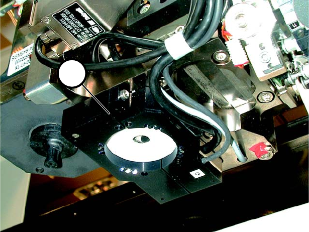
Fig. 7.0.1 Oblique Lighting Ready for Operation
7.1 Contents of Retrofit Kit
– Oblique lighting blue 00116172-01
– Retrofitting Instructions 00192211-01
1
Oblique Lighting for SIPLACE 80 S-20 /F4/S-23/ F5 /HS-50/HF Retrofit Instructions
05/15 Issue 8.1 Moving Out the Movable Component Changeover Table
23
8 Mounting
8.1 Moving Out the Movable Component Changeover
Table
(Note: You will find detailed instructions in the User Manual for the placement machine.) 8
► Turn the placement machine ON at the main switch.
► Open the safety hood protecting gantry 1.
► Unlock and lift the movable component changeover table and move it out as far as possible
without damaging the cables.
► Turn the placement machine OFF at the main switch.
► Run cable and hose connections to the movable component changeover table.
► Pull the movable component changeover table all the way out.
8.2 Moving Out the Component Changeover Table
(Note: There are detailed instructions in the User Manual for the placement machine.)
► Unplug the power connector for the component changeover table.
► Unplug the communications connector.
► If necessary, disconnect the coupling for the component changeover table compressed air sup-
ply.
► Push the pallet jack under the component changeover table.
► Loosen the 2 socket hex head screws fastening the component changeover table.
► Open the horizontal clamping devices.
► With the pallet jack, lift the component changeover table carefully until the centering pins are
no longer in the holes.
► Now move the component changeover table out.