4Q4CEIM.pdf - 第18页
Page 1-6 B) Ethernet cable (PT) In using PT, it is necessary to use the ethernet cable. Connect the cable with the hub in the machine and the computer to which the PT is installed with the ethernet cable. Ethernet cable …
Page 1-5
INSTALLATION
1
M/C
950
116
H
A
1
2
3
Preparations for Installation
1-1-3 Foundation
It requires the flat concrete floor for the foundation of installation.
Confirm the enough endurance of the soil.
• Endurance of the soil : more than 6570 N/m
2
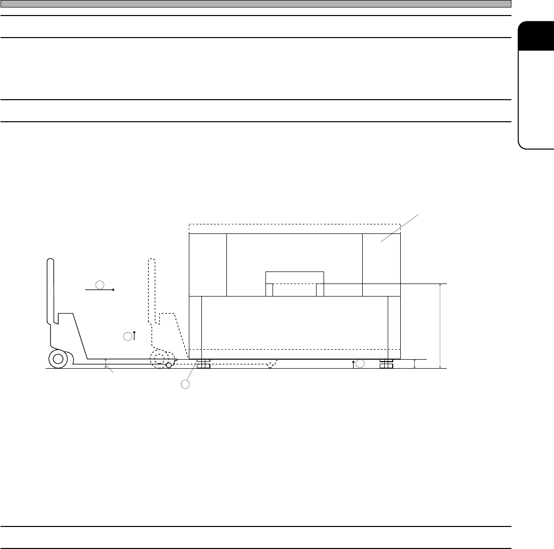
1-1-4 Lifting
A) Use the forklift for loading to or unloading from the truck.
In case of using crane, the special parts are necessary.
B) In case of replacement within the factory.
1 Rotate the leveling block A, and lift it so that the bottom of the machine is higher than the pallet
truck (H).
2 Place the pallet truck under the machine.
3 Lift the pallet truck to lift up the machine. (The number of pallet truck usage is different up to its
weight.)
4 Carry it to the right position.
1-1-5 Arrangement Diagram
Draw the reference line of the machine by the arrangement diagram.
Board transfer
height
493C-004E
4Q4C-E-IMA01-A01-01
Page 1-6
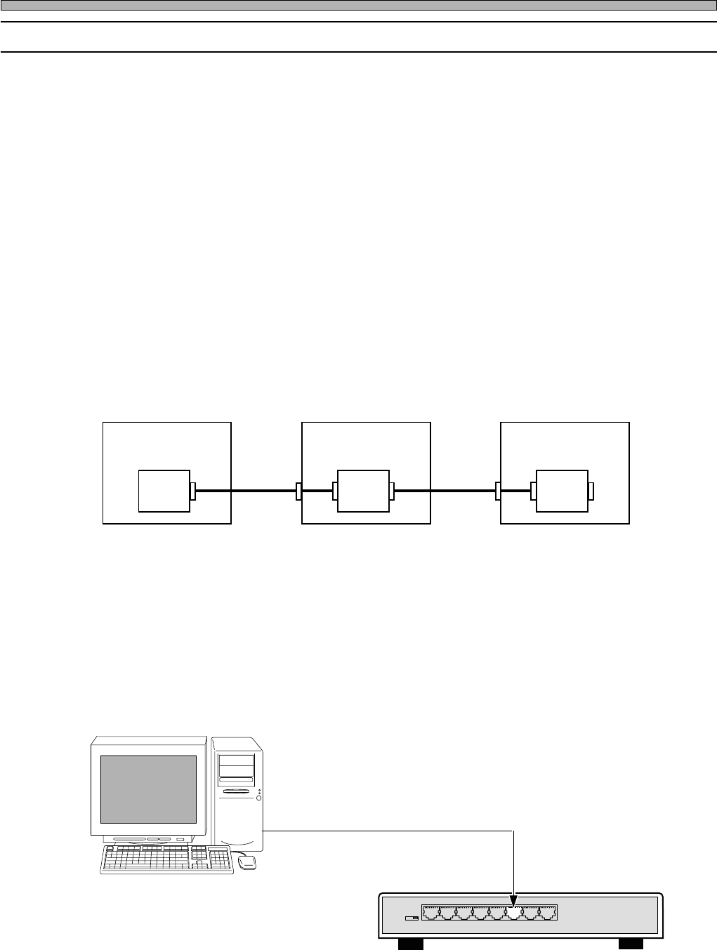
B) Ethernet cable (PT)
In using PT, it is necessary to use the ethernet cable.
Connect the cable with the hub in the machine and the computer to which the PT is installed with
the ethernet cable.
Ethernet cable (10m)
Ethernet 8 port hub
Connected to port 3
3Y3C-027E
3N3C-002E
Preparations for Installation
1-1-6 Board Setting / Ethernet Cable
A) Board setting
1) Stand alone : CN00 1-2 short (Line air pressure)
2) Line connection : CN00 1-2 open (Line air pressure)
NF18CX
∗
1
FOK 2-3 short
3) : CN00 1-2 short (Line air pressure)
NF18CX FOK 1-2 short
∗1) The “X” at the end may vary according to models.
Line signal specification
Outline
Connect signals for board transport between the pre-process and the post-process, production
end, air pressure, etc. with one cable between machines.
CN01
Control
box
Machine 1
CN01
Control
box
Machine 1
CN01
Control
box
Machine 1
CN00CN00
CN00 : Connector to the previous process
CN01 : Connector to the next process
Connection with other
maker's machine
4Q4C-E-IMA01-A01-02
Personal computer (PT)
Page 1-7
INSTALLATION
1
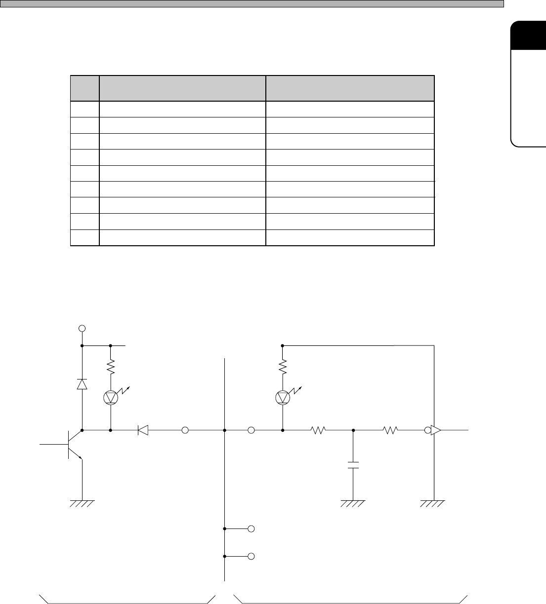
Construction of the hardware
Connector pin arrangement and names
Signal interface
Output circuit
Input circuit
Maximum of 20 circuits
TD62107 Equivalent
Built-in
clamp
diode
Common
Vss-12 V or 24 V
+12 V
4.7 kΩ
510 kΩ
10 kΩ
0.01 µF
CMOS 4584
Equivalent
6A4C-IL008
The common terminal of the clamp diode
built in TD62107P should be opened when
using this interface. (Do not use 62107 for
the solenoid driver because of the reason
above.)
Preparations for Installation
4Q4C-E-IMA01-A01-01
CN00
GND
Line air pressure
Unused
Unused
Unused
F-OK contact point
Operation-end
Operate line
F-OK
CN01
GND
Line air pressure
Unused
Line out 1
+12 V
Line out put
Operation-end
Operate line
R-READY
1
2
3
4
5
6
7
8
9