4Q4CEIM.pdf - 第26页
Page 1-14 4Q4C-E-IMA01-A01-01 = MEMO =
Page 1-12
5) Connecting the surrounding devices
Install the status Indicator according to the procedure of 1-3.
In case of the line specification, connect a signal cable as 1-1-6.
6) Connecting the power source and air source
Connect the primary power source and the primary air source.
7) Adjust the air pressure
Adjust the regulator so that the secondary air pressure is 0.49 MPa.
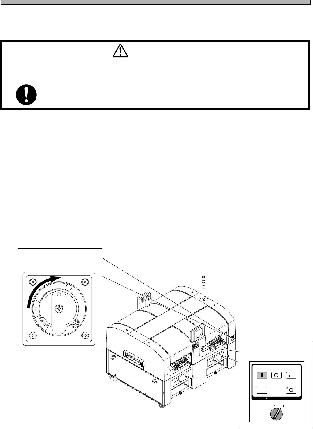
8) Power supply
(1)Turn the main power switch ON.
(2)Turn the servo select switch ON.
Then, start the operation by following the procedure on operating manual.
Installing Procedure
4Q4C-E-IMA01-A01-01
(2) Servo select switch
M 92E
POWER AND AIR SOURCES SHOULD BE CONNECTED AT THE LAST OF
INSTALLING OPERATION.
If they are connected earlier, you may get an electric shock or injured.
WARNING
R
E
L
E
A
S
E
T
R
I
P
O
F
F
O
N
R
E
S
E
T
(1) Main power switch
OFF ( )
ON ( )
SERVO
STOP
UNLOCK
STEP
START
SELECT
KEY LOCK
KEY LOCK
4U4C-901EU
Page 1-13
INSTALLATION
1
4Q4C-E-IMA01-A01-00
1-3 Assembling Procedure of Surrounding Devices
1-3-1 Setting the Status Indicator
1) Install the indicator to the main body.
• Fix it by tightening the hexagonal nuts from the inside of the cover.
2) Connect the indicator signal cables to the indicator connection terminal.
• Insert the plug set at the end of the cable to the socket on the main body, with a hook.
Socket
Plug
Hexagonal nuts
Red
Yellow
Green
M 93E
BEFORE INSTALLATION OF ATTACHED EQUIPMENT, MAKE SURE THAT
POWER AND AIR SOURCES ARE NOT CONNECTED WITH THE BODY OF
MACHINE.
If they are connected, you may get an electric shock or injured.
WARNING
183C-IL009

Page 1-14
4Q4C-E-IMA01-A01-01
= MEMO =