4Q4CEIM.pdf - 第22页
Page 1-10 1-2 Installing Procedure NOTICE Machine installation is conducted by experts. Here, the outline of the procedure is described. For rearranging the machine, make contact with the service department. 1) Machine t…
Page 1-9
INSTALLATION
1
Preparations for Installation
4Q4C-E-IMA01-A01-01
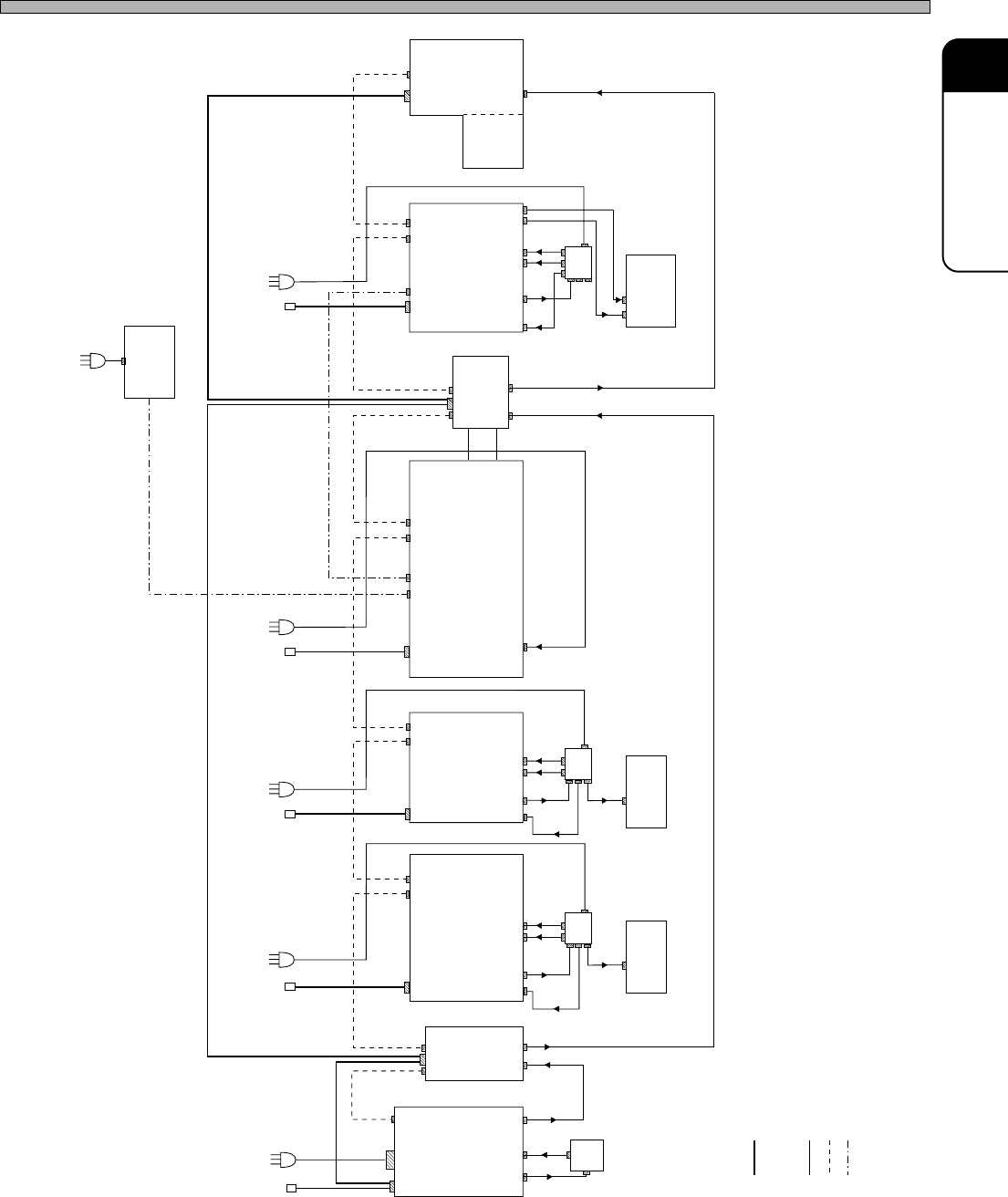
4Q4C-002E
TB
200V
230V
200V
POUT
PIN
LD12F RV10C
SP28P
TB
100V
400V
400V
200V
200V
Atomosphere
temperature
control unit
POUT
CN01CN00
CN01
M.T
200V
CN00
M.T
CN01 CN00 CN01
M.T
BD20S CM201/202
CN00 CN01
TB
100V
400V
400V
200V
100V
MC12C
CN00 CN01
PIN
200V
POUT
200V
M.T
CM120
CN00 CN01
TB
100V
200V
400V
400V
400V
LD12B
200V
PIN
CN00
200V
100V
A10
A3
DT20F
-20U
3 400V
Atomosphere
temperature
control unit
φ
3 400V
φ
3 400V
φ
3 400V
φ
1 230V
φ
: Air
: Main terminal
: Transmission box
: Power
: Line signal
: Ethernet
M.T
TB
PT
1 230V
φ
Page 1-10
1-2 Installing Procedure
NOTICE
Machine installation is conducted by experts.
Here, the outline of the procedure is described.
For rearranging the machine, make contact with the service department.
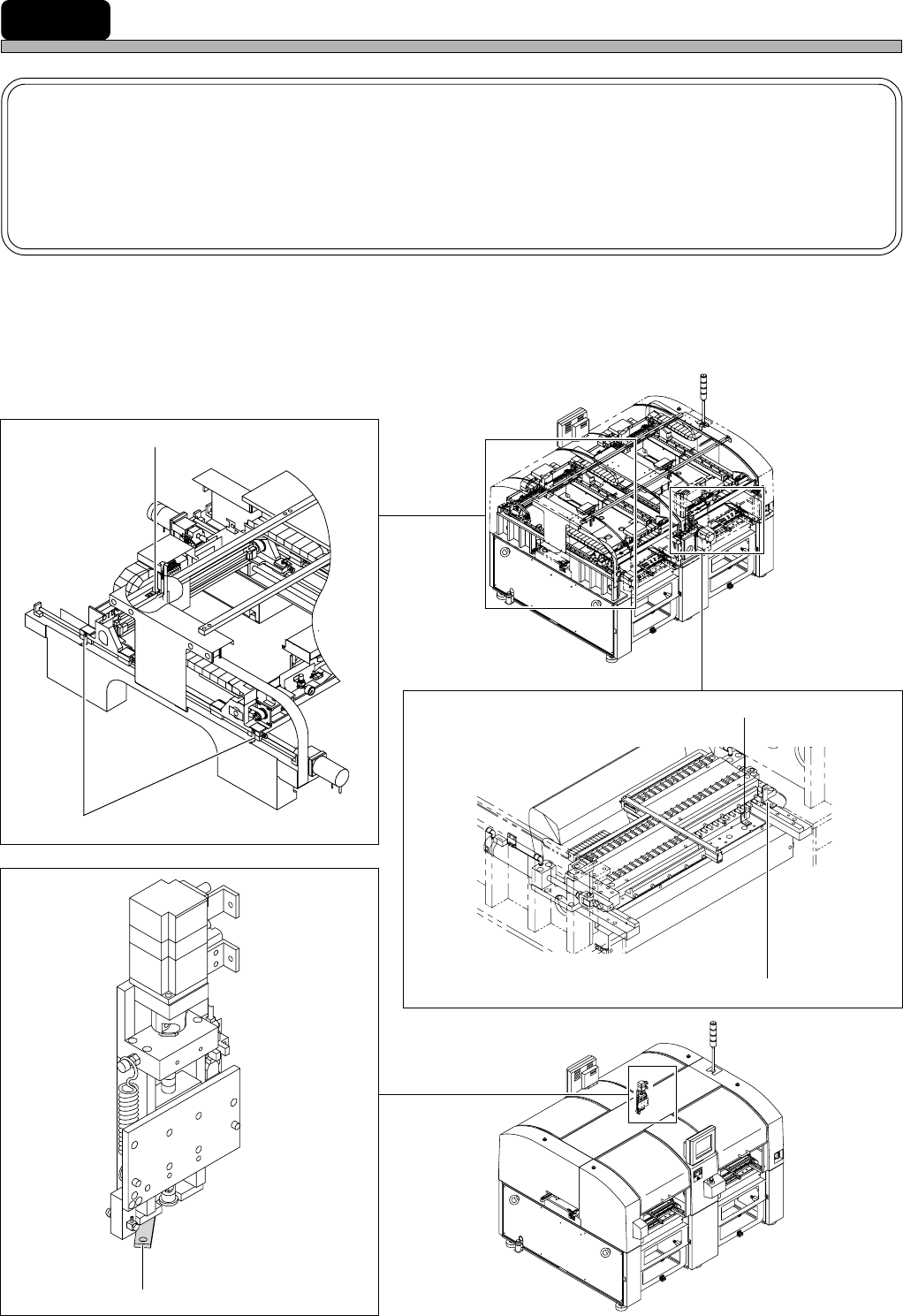
1) Machine transport condition
During the machine transport, X-axis, Y-axis, Z-axis, feeder base drawer, and sending cylinder
changer (it is for the double feeder) are fixed with the fixing brackets (red) to prevent removing.
∗ Half number of fixing brackets is necessary for CM201.
4Q4C-E-IMA01-A01-01
4Q4C-010CC0
4Q4C-011AC0
4U4C-150FC1
4Q4C-904E
4U4C-AC00
X-axis fixing brackets (4 points)
Y-axis fixing brackets (8 points)
Z-axis fixing brackets (4 points)
Fixing brackets for sending cylinder changer (4 points) (option)
Fixing brackets for feeder base drawer (8 points)
Page 1-11
INSTALLATION
1
2) Machine placement
Place the machine along the reference line. Adjust the machine position so that the board is
smoothly transferred between the previous and the next processes. (Direction and height of
transfer)
3) Removing the fixing bracket (red)
Remove all brackets (red). Keep the removed brackets.
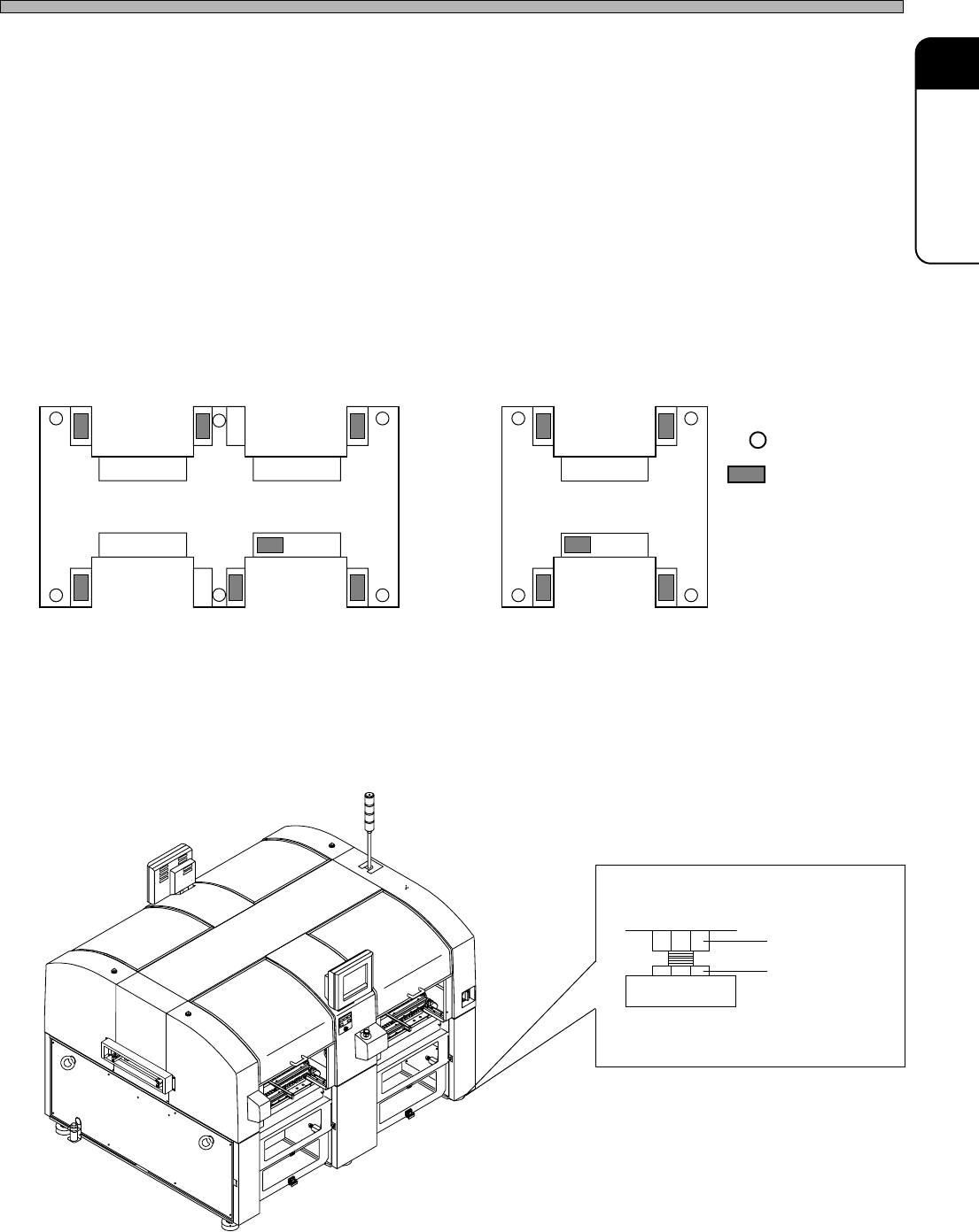
4) Setting the accurate level
Install the level (0.02 mm / m / div) to the position described below.
Adjust it so that it gets less than a scale (0.02 mm / m) by using the adjustment bolt.
After adjustment tighten the locking nut.
Locking nut
Installing Procedure
4Q4C-E-IMA01-A01-01
Adjustment bolt
Level pad
CM202-DU, CM202-DHU
CM201-DU
: Level pad
: Installing
position
of the level
4U4C-901EU
1B4C-840E
4Q4C-IL001E