KE-3010_SPE_EN.pdf - 第59页
- 54 - 6.3.3. Feeder calibr ation jig This Jig is f or calibrating a f eeder while monitoring th e c omponent pick - up position with a CCD camer a. If you check and cali brate the pick position on a regular bas is, you …
- 53 -
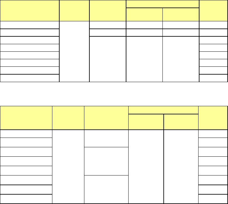
2) Common specifications
EF series Electric feeder
Name Voltage
Maximum
allowable
current
Dimensions
Mass
Total
length (L)
Height
(H)
EF02HS / EF08HS
DC24V
1.8A
660mm
335mm
2.5kg
EF08HD
2.1A
911mm
455mm
3.0kg
EF12FS
1.8A 700mm 335mm
3.0kg
EF16FS / EF24FS
3.5kg
EF32FS / EF44FS
4.0kg
EF56FS
4.5kg
EF72FS
5.0kg
EF88FS
5.5kg
RF
series Electric feeder
Product code Voltage
Maximum
allowable
current
Outside dimensions
Mass
Total
length L
Height H
RF04AS
DC24V
DC5V
3.5A(DC24V)
0.15A(DC5V)
530mm 300mm
1.35kg
RF08AS
1.3kg
RF12AS
1.5A(DC24V)
0.15A(DC5V)
1.8kg
RF16AS
1.8kg
RF24AS
2.2kg
RF32AS
1.8A(DC24V)
0.15A(DC5V)
3.0kg
RF44AS 3.2kg
RF56AS 3.4kg
3) O
ptions
① RFID tag attachment kit
By attaching a RFID tag on an ETF feeder currently used, you can manage the feeders
with the production management system.
② Scissors (Tape cutting jig A, and B)
A positional adjustment between the tape feeder used during the production and a new
tape feeder to be connected can be accurately and quickly made by cutting the tapes
with dedicated scissors when they are spliced.
・Tape cutting jig A: Available for feed pitch (4, 12, 20, 28, 36, 44, 52).
・Tape cutting jig B: Available for feed pitch (8, 16, 24, 32, 40, 48, 56).
③ Joint tape
This is a tape that splices an old tape reel and a new tape reel.
A dedicated type for each tape width is available.
- 54 -
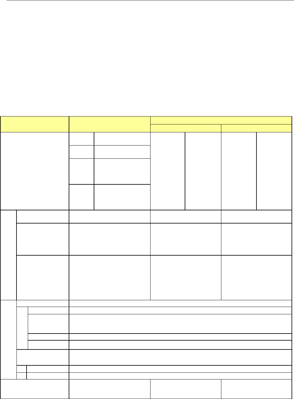
6.3.3. Feeder calibration jig
This Jig is for calibrating a feeder while monitoring the component pick-up position with a
CCD camera. If you check and calibrate the pick position on a regular basis, you can
maintain the stable pick-up capability.
On support of IFS-NX *Only IFS-NX for a mechanical feeder (JM01) is available.
As an option, if you attach the RFID reader (antenna) onto the jig main unit, you can manage
the maintenance state of each feeder with the IFS-NX system, which records the
maintenance history, the frequency of usage and others for each feeder; For example, the
system indicates a feeder of which pick-up ratio became lower, and displays a list of feeders
that need to be calibrated according to the maintenance interval settings.
* T
o use “Intelli feeder calibration Jig with LCD monitor, “IFS-NX” is required.
Refer to the “IFS-NX PRODUCT SPECIFICATIONS” for “IFS-NX.”
Note 1: A jig tape and tools are required separately when adjust feeder.
Note 2: The RFID correspondence of the tape feeder is necessary for using the RFID function of the
production management system.
For Mechanical Feeder
(
JM01
)
For Electric Feeder
EF-ATG
RF-ATF
Feeders
*See Note1
ATF
8mm to 24mm
*Note2
EF series
electric
f
eeder
8mm
12mm
16mm
24mm
32mm
44mm
56mm
RF series
electric
feeder
4mm
8mm
12mm
16mm
24mm
32mm
44mm
56mm
CTF,
CTFR
8mm
*Note2
FTF
FTFR
8mm to 72mm
*Note2
32mm to 56mm
*Note2
BF
BF10AS,BF11AS,
BF12BS,BF12CS,
BF25CS,BF28CS,
BF28RS
Specifications
Power supply
Select 100 V - 120 V
or 200 V - 240 V
100 - 240V 100 - 240V
Outer dimension
L=290mm ,
H=480mm,
W=157mm
L=400mm ,
H=710mm,
W=240mm
L=300mm ,
H=710mm,
W=250mm
(
Except for the PC and
the power supply Box)
Mass
- Adjustment jig main unit:
12 kg or less
(including the CCD camera
and lens section)
- Master feeder: 2 kg
- Monitor: 4kg
- Adjustment jig main
unit: 20 kg or less
(including the CCD
camera and lens section)
- Master feeder: 3.5 kg
- Monitor: 4 kg
- Power supply: 2.5kg
- Adjustment jig main
unit: 20 kg
(including the CCD
camera and lens section)
- Master feeder: 3.5 kg
- Power supply: 2.7kg
Environment
During operation
Temperature
10°C to 35°C
Accuracy
guaranty
temperature
20°C to 25°C
Humidity
30% to 80%RH (No condensation)
Altitude 1,000m or less
Transportation or
storage
Temperature
-15°C to 70°C
Humidity
20% to 95%RH (No condensation)
Option for IFS-NX
Options for the RFID system
- Controller (MPC)
- Antenna
- -
- 55 -
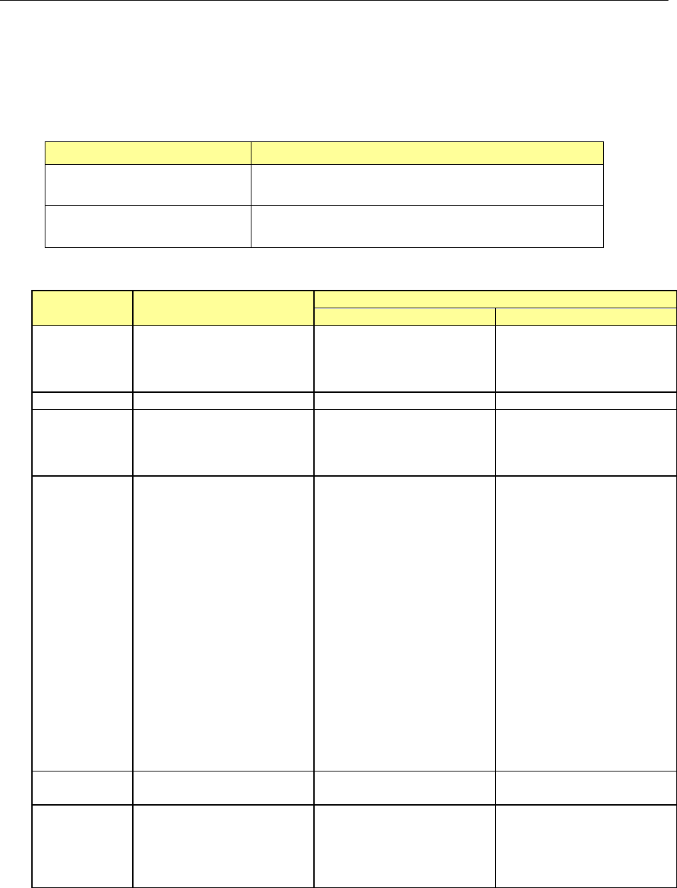
6.3.4. Feeder setup stand
This is platform for attaching a tape reel onto a tape feeder. Since it allows you to attach a
tape reel on a tape feeder while keeping the tape feeder in position, the tape attachment
capability is improved and it also functions to prevent a tape feeder from falling.
T
wo types of packages of feeder setup stand designed for a mechanical feeder are available
in response to applications.
Type Application
Feeder setup stand
(With a stand)
Equipped with pedestal stand: can be installed as desired.
Feeder setup stand
(without a stand)
A user has to fix the platform on a table or similar
substance with screws.
(
1) Specifications
For a mechanical tape
feeder
For an electric tape feeder
FSS (For EF series)
RF-FSS (For RF series)
Power
supply
―
Input side:
90 to 250 V AC
Output side:
DC ± 24 V (± 10 %)
Input side:
90 to 250 V AC
Output side:
DC 24 V DC 5 V
Frequency
―
Input side: 50/60 Hz
Input side: 50/60 Hz
Current ―
Input side: 1.5 A
(maximum)
Output side: 4.2 A
(maximum)
Input side: 1.4 / 0.7 A
(100V / 200V) typ.
Output side: 3A
(maximum)
Outer
dimensions
Platform equipped with a
stand:
* When including a
f
eeder support section
L = 666 mm,
W = 400 mm,
H = 977 ± 50 mm
* Base side only
L = 550 mm,
W = 400 mm,
H = 977 ± 50 mm
* P
latform without a
stand:
L = 187 mm,
W = 127 mm,
H = 187 mm
L=550mm,
W=470mm,
H=950±50mm
L=550mm,
W=470mm,
H=950±50mm
Mass
20. kg (with a stand)
1.5 kg (without a stand)
25 kg (with a stand) 25 kg (with a stand)
Number of
feeders to
which
power can
be supplied
― 1 1
* The outer dimensions and mass described above indicate values to be applied when
any
feeder is not mounted on the platform.