00196678-0102_RI_CAN-Knoten_X-Serie70x_De+EN.pdf - 第51页
Installation Running the CAN Nodes Option Cable Retrofit Instructions CAN Node X Series SW70x 51 6-9: Circuit diagram for 1 wire hub module [03041473-xx] 6-8: Removing the 1 wire hub module [03041473-xx] X Remove the 1 w…
Installation
Running the CAN Nodes Option Cable
50 Retrofit Instructions CAN Node X Series SW70x
6.3 Running the CAN Nodes Option Cable
NOTE:
In placement areas with only one gantry, the component trolley feed-in device is fitted in the
innermost position of location 2 or 4. In this case, the component trolley feed-in device needs to
be pulled out slightly. In placement areas with only one gantry, the component trolley feed-in
device is fitted in the innermost position of location 2 or 4. In this case, the component trolley
feed-in device needs to be pulled out slightly. Please read the service manual for the X series
prior to this.
When fitting, first tighten the fitting screw and then the screws on the inner side of the machine.
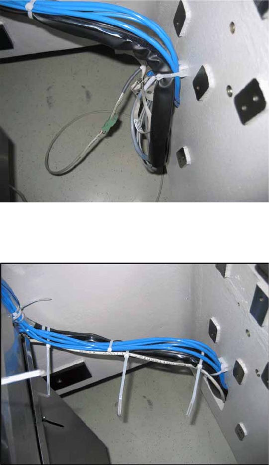
6-6: Cable routing for CAN nodes to back of component trolley feed-in device
X Route the cable from the CAN nodes along the
existing cable tree to the back of the
component trolley feed-in device and fix in
place with cable ties.
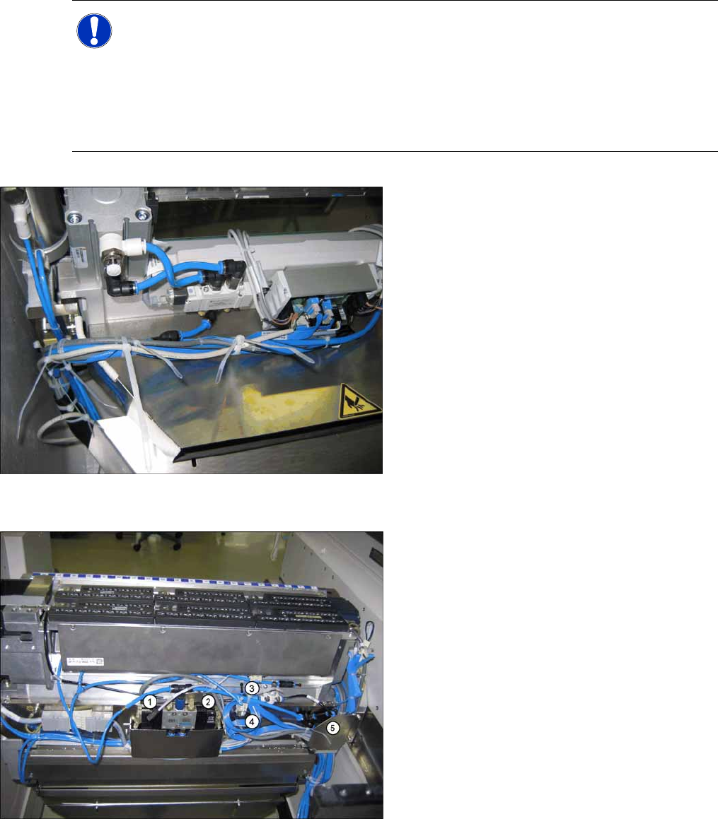
6-7: Cable routing for CAN nodes to back of component trolley feed-in device
X Run the option cables to the back of the
component trolley feed-in device. The cables
must be routed under the cover plate (5).
X Run the option cables and fix in place with
cable ties.
(1) Cable of feed-in device for X series: nozzle
station [03053223-xx]
(2) Cable feed-in device X series: reject bin
[03053229-xx]
(3) Cable of feed-in device for X series: NC
CAN nodes NC row 1 [03053225-xx]
(4) Cable of feed-in device for X series: NC
CAN nodes NC row 2 [03053225-xx]
Installation
Running the CAN Nodes Option Cable
Retrofit Instructions CAN Node X Series SW70x
51
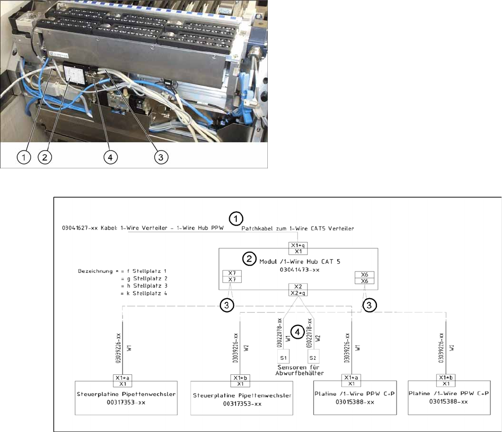
6-9: Circuit diagram for 1 wire hub module [03041473-xx]
6-8: Removing the 1 wire hub module [03041473-xx]
X Remove the 1 wire hub if still present and
connect the new cables to the options fitted.
See also Reject bin query SIPLACE X series /
D3, issue 11/2006 [00194716-02]. or Assem-
bly instructions for nozzle changer CPP/
C&P20A (from SW 702) SIPLACE X series, is-
sue 06/2009 [00196432-01]
(1) Patch cable [03041326-xx] to 1 wire distributor
[03040219-xx]
(2) 1 wire hub module [03041473-xx]
(3) Cable to nozzle changer (4) Cable for component reject bin query
Installation
Running the CAN Nodes Option Cable
52 Retrofit Instructions CAN Node X Series SW70x
6-10: Connecting cable "Power CAN nodes NC/TC [03047464-xx]" at
location coding +24V supply (cable W3 connector designation X3*p
[03019056-xx]).
X Run the "Power CAN nodes NC/TC
[03047464-xx]" cable along the cable tree to
the X3*P connector and fix in place with cable
ties. This X3*P connector is part of the "X
series /feed-in device FCU signaling
[03019056-03]" cable on the component
trolley feed-in device cable tree. (See also the
circuit diagram).
6-11: Cable routing for CAN nodes to back of component trolley feed-in
device