00196678-0102_RI_CAN-Knoten_X-Serie70x_De+EN.pdf - 第61页
Installation CAN Node Conversion on C&P20 Nozzle Changer Retrofit Instructions CAN Node X Series SW70x 61 6.5 CAN Node Conversion on C&P20 Nozzle Changer 6-22: Conversion C&P20 nozzle changer X Check the func…
Installation
Removing the 1 Wire Infrastructure
60 Retrofit Instructions CAN Node X Series SW70x
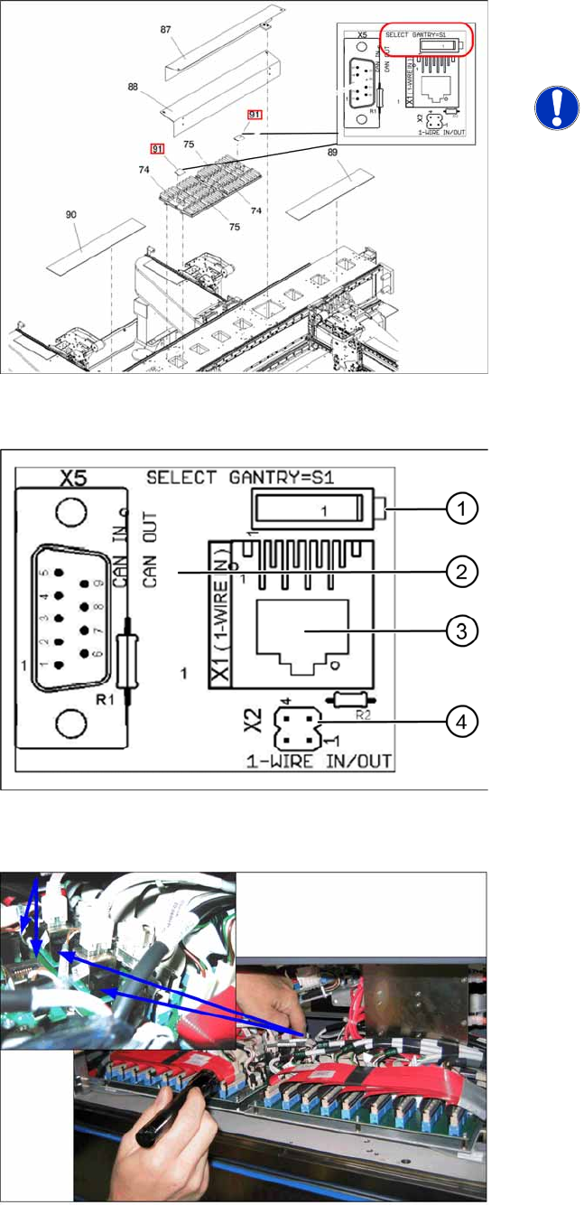
6-19: 1 wire CAT5 gantry IGUS board [03042214-xx]
X For each placement area, switch over the S1
switch on the 1 wire CAT5 gantry IGUS. (Also
see next diagram).
NOTE:
If this switch is not switched over, the
temperature correction values will be
calculated for the wrong gantry, which
can lead to placement inaccuracies
and which will show temperature error
messages for the wrong gantry.
6-20: 1 wire CAT5 gantry board [03042214-xx]
One wire CAT5 gantry board
1. Switch:
Setting for 1 wire:
Position down = gantry 1/2,
Position up = gantry 3/4
Setting for CAN nodes:
Position up = gantry 1/2,
Position down = gantry 3/4
2. This board is located directly on the CAN bus
connector of the trailing interface.
3. Connection CAT5 cable from one wire CAT5
distributor
4. X2 connection to second gantry in placement
area.
6-21: Switching over the switch for the 1 wire CAT5 interface board
Installation
CAN Node Conversion on C&P20 Nozzle Changer
Retrofit Instructions CAN Node X Series SW70x
61
6.5 CAN Node Conversion on C&P20 Nozzle Changer
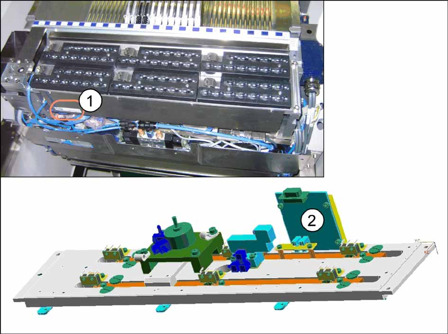
6-22: Conversion C&P20 nozzle changer
X Check the function state (FS) of the nozzle changer. This must be higher than FS03. If this is not the
case, remove the nozzle changer. Also remove the cover sheet and replace the 1 wire NC C&P20
board [03015388-xx] with a CAN-NC C&P20 board [03045735-xx]. Perform this check for all C&P20
nozzle changers used in the machine and replace them where necessary.
(1) Position of nozzle changer item number (2) CAN NC C&P20 board [03045735-xx]
Installation
Converting the C&P20 Nozzle Station Dismantling the Nozzle Station 1 Wire Hub Valve
62 Retrofit Instructions CAN Node X Series SW70x
6.6 Converting the C&P20 Nozzle Station
6.6.1 Dismantling the Nozzle Station 1 Wire Hub Valve
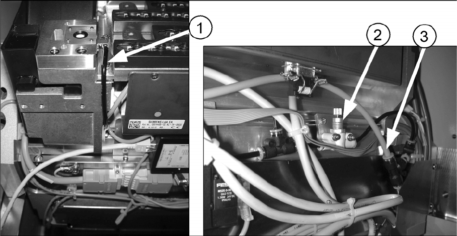
6-23: Running the hose to the nozzle station [03045404-xx]
X Disconnect the T-piece from the pneumatic supply (3).
X Remove the T-piece for the nozzle station from the component trolley feed-in device.
X Dismantle the fine throttle (2).
X Disconnect the hose (1) from the nozzle station.
X Close the open outlet of the T-piece with a dummy plug.
(1) Hose for nozzle station (2) Fine throttle
(3) T-piece