00198146-01_AI_120V_TX12_de_en.pdf - 第41页
Assembly Instructions / Montageanleitung SIPLACE TX Series Option 120 V 04/2017 1 Introduction 1.2 Preparatory Work... 41 1.2 Preparatory Work... Purpose and scope Before performing any preventive maintenance work, conve…
1 Introduction
1.1 Safety Instructions
Assembly Instructions / Montageanleitung SIPLACE TX Series
Option 120 V 04/2017
40
Machine switched off at the main power switch and disconnected ...
DANGER
Hazardous voltages in the power supply unit!
The power supply unit houses components (capacitors) that can carry hazardous voltages
for about five minutes after the machine has been switched off and the power plug has
been unplugged.
► Wait at least five minutes before your start working on the power supply unit.
► Work on the power supply and the contactor safety breaker (CSB) must only be car-
ried out by service engineers of ASM Assembly Systems GmbH & Co. KG or by ma-
chine owner service engineers who have been trained by ASM.
Compressed air conditions in the machine after switching off at the main switch
When the system is switched off at the main power switch or if the power supply fails, the electric-
ally-controlled main valve of the compressed air unit closes. The pressure will drop to 0 MPa
(0bar) within five seconds.
1.1.4 Safety Instructions for Work on the Cutting Device
WARNING
Risk of injury when working near the tape cutter.
When working in the area of the tape cutter, move the component trolley out of the machine
and disconnect the machine from the mains supply and the compressed air supply.
► Wait until the operating pressure has dropped to 0 MPa.
► Always secure the machine against unauthorized reactivation.
► Do not reach into the tape cutter.
CAUTION
Risk of injury when performing service work on the tape cutter.
Never support the tape cutter on your body, e.g., on your knees or thighs. Do not place
your feet under the tape cutter.
► Wear appropriately thick protective gloves.
► When removing/fitting the tape cutter, hold it only outside on the left and right.
1.1.5 Safety Instructions for the Gantry
CAUTION
Moving the gantry can damage the placement head.
When moving the gantry, observe the following:
► NEVER move the gantry by pushing with your hands against the placement head.
► NEVER push the gantry while the Z axis is lowered.
1.1.6 Safety Instructions on Hazardous Materials
CAUTION
Observe the safety data sheets
Observe the applicable safety data sheet, when handling hazardous materials (e. g. Loctite
241, ethanol).
Assembly Instructions / Montageanleitung SIPLACE TX Series
Option 120 V 04/2017
1 Introduction
1.2 Preparatory Work...
41
1.2 Preparatory Work...
Purpose and scope
Before performing any preventive maintenance work, conversion work or service work, a procedure
of locking and tagging must be followed and warning signs must be attached if not stated other-
wise. If it is not necessary to switch off the machine, it is explicitly mentioned.
The procedure, when followed correctly, eliminates the possibility of an employee being injured.
NOTICE
Additional safety measures
This procedure represents the minimum lock out and tag out requirements for the machine
during preventive maintenance work and service work. Any additional safeguards needed
to complete work safely can be specified by facilities supervision, the safety officer, the
safety committee and the health department.
Description
Whenever it becomes necessary to isolate, control and release energy, the following procedure is
to be followed.
► Notify all affected employees.
► Switch off the machine and all additional devices. Carry out all normal stopping procedures:
ð Press the STOP button.
ð Shut down the station computer.
ð Switch off the machine using the main switch.
► Isolate the machine from all its energy sources:
ð Shut off the compressed air supply.
ð Shut off the main power supply.
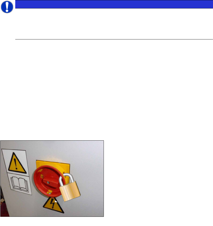
► Lock out the machine.
ð Attach a lock wherever possible:
Fig.2: Attaching a padlock to the main power switch
Secure Main Switch
► Secure the main switch with a padlock.
► Alternative: Attaching warning signs:
If a machine can be locked, it must be.
However, there are situations where energy isolating devices cannot accommodate locks. In
these cases, the energy isolating devices must be tagged to warn employees that the ma-
chine is de-energized for servicing. The tag or label must be securely fastened, it must be
placed in a position visible to all and it may only be removed by the person who attached it.

1 Introduction
1.2 Preparatory Work...
Assembly Instructions / Montageanleitung SIPLACE TX Series
Option 120 V 04/2017
42
► Release of stored energy:
Energy stored as compressed air in the compressed air supply or electrical energy stored in
electrolytic capacitors must be released by appropriate means.
After switching off the machine, wait until the voltages have discharged and the compressed
air has released, so that work can be performed without any risk.
DANGER
Checking for absence of voltage!
► Before you start working, check the power supply for absence of voltage and observe
the waiting times!
► Testing the lock out:
The lock can be easily tested by pressing the START button.
The following steps must be taken to restore the machine to operation.
► Check the workspace. Authorized employees should remove all of their tools and reinstall all
safety features.
► Notify all affected employees.
► Before removing even one lock or tag, inform all workers in the affected area that the machine
is going to be restarted.
► Remove all locks/tags.
Every authorized employee must remove his own lock and shut it away.
► Switch on the machine. Make sure that authorized staff check the equipment in operation to
ensure that all repairs were performed correctly.
Testing
Service personnel may test circuits by energizing them briefly without suspending the Lock Out /
Tag Out Procedure. This may only be done when no other work is being performed by any other
person on the equipment being tested.
It is extremely important that all remote START switches are tagged with the "Do Not Operate" tag
to prevent inadvertent operation of the equipment during these periods.
Responsibilities
●
It shall be the responsibility of the maintenance and service personnel to make sure this pro-
cedure is adhered to.
●
It shall be the responsibility of the maintenance and service personnel's immediate supervisor
to instruct their personnel on this procedure.
●
It shall be the responsibility of the Safety Officer to administer the Lock Out / Tag Out Proced-
ure.