00198146-01_AI_120V_TX12_de_en.pdf - 第56页
3 Installation 3.5 Performing Final Work Assembly Instructions / Montageanleitung SIPLACE TX Series Option 120 V 04/2017 56
Assembly Instructions / Montageanleitung SIPLACE TX Series
Option 120 V 04/2017
3 Installation
3.4 Installing the socket protection
55
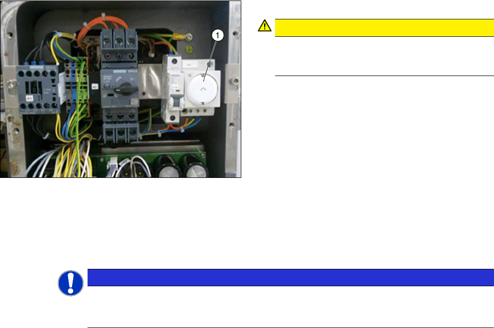
3.4 Installing the socket protection
Fig.18: Socket protection
► Mount the socket protection(1).
CAUTION!
Do not use the service socket any longer
After the 120 V option is installed, the service
socket must no longer be used.
.
3.5 Performing Final Work
► Refit all covers.
► Hook the waste tape chute back into place.
NOTICE
DIN EN 60 204 Safety Inspection
► Perform an electrical safety inspection after the conversion work has been completed.
Observe the relevant country-specific regulations and laws for this.
The installation is now complete.
3 Installation
3.5 Performing Final Work
Assembly Instructions / Montageanleitung SIPLACE TX Series
Option 120 V 04/2017
56
Assembly Instructions / Montageanleitung SIPLACE TX Series
Option 120 V 04/2017
4 Appendix
4.1 Excerpts from the Service Manual
57
4 Appendix
4.1 Excerpts from the Service Manual
The following chapters are excerpts from the service manual. For more information, refer to the full
service manual for your machine.
●
Service Manual SIPLACE TX-Series [DE:00198149‑xx] [EN:00198150‑xx]
4.1.1 Electrical Checks
DANGER
Observe the safety instructions
There is a risk of dangerous touch voltages and short circuits occurring in power supplies
which have been made accessible and are connected for measurement purposes.
Nonobservance of these safety instructions may cause injury to personnel and dam-
age to the machine!
Measurements may only be performed by specially trained service technicians with appro-
priate qualifications and expertise.
► Observe the safety instructions in this manual and in the user manual.
Tools and Equipment required
●
Digital voltmeter, class 1,5
●
Test cable with test probes or terminals
CAUTION
Take care not to damage the supply lines!
Make sure that the main power cable and supply cables in the machine are not trapped and
that the insulation is not damaged.
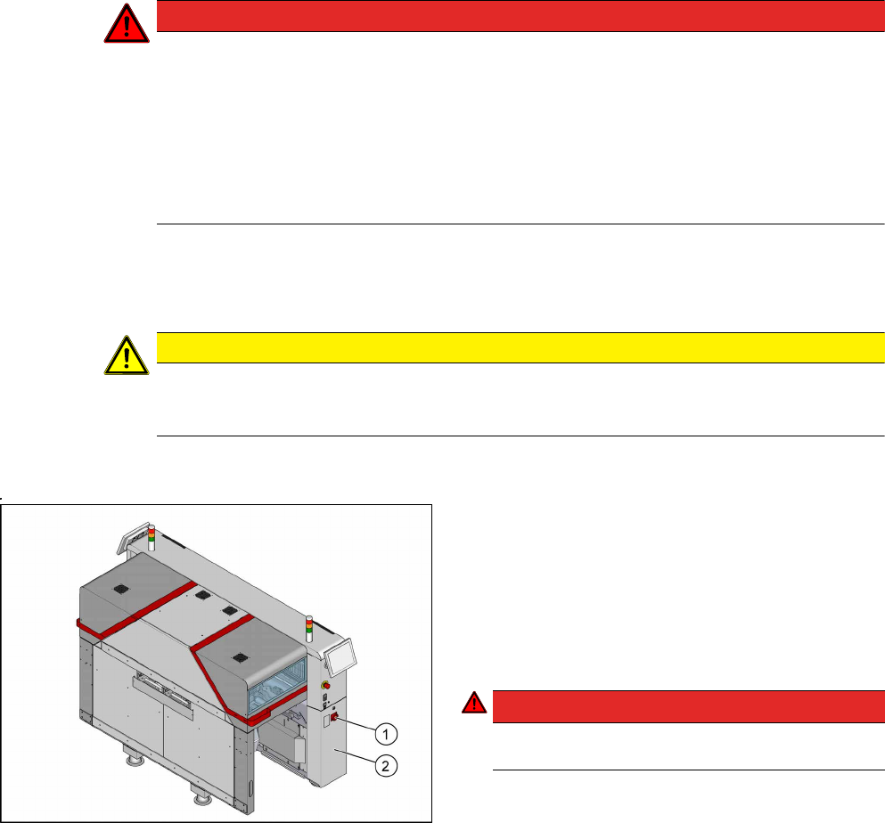
Preparation
Fig.19: Main switch
► End all placement operations and switch the ma-
chine off at the main switch(1).
► Disconnect the machine from the main power
supply.
► Open the lock on the power supply cover(2).
► Pull the power supply out towards the front (see
Pulling out the Power Supply).
► Reconnect the machine to the power supply.
DANGER!
Careful: There may be dangerous touch voltages
in the vicinity of the open power supply!
.
► Switch the machine on again at the main switch
and start it up.
Voltages
► Measure the required voltages.
Please refer to the relevant circuit diagram for your machine for details of the various voltages.