00195467-01_Installation Manual Setup Center 2.2.pdf - 第11页
Installation Manual SIPLACE Setup Center 2.2 4 System component s and configurations 4.1 System components 4.1.1 Setup Center A complete installation of SIPLACE Setup Center requires: • SIPLACE Pro Interface SIPLACE Setu…
SIPLACE Setup Center 2.2 Installation Manual
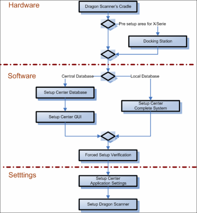
Fig. 3-2 The installation procedure
10 of 90
Installation Manual SIPLACE Setup Center 2.2
4 System components and configurations
4.1 System components
4.1.1 Setup Center
A complete installation of SIPLACE Setup Center requires:
• SIPLACE Pro Interface
SIPLACE Setup Center consists of the following components:
• SIPLACE Setup Center GUI
• SIPLACE Setup Center Database
• Database Backup Tool
• Error Reporting Tool
In addition the following tools can be installed:
• Setup Selection Assistant
• SIPLACE Pro Trace Config Assistant
4.1.2 Dragon Scanner
The Setup Center supports the radio-controlled scanner system „Dragon M101“ by Datalogic.
This scanner has a four-line display and supports 1D barcodes only.
Communication between the scanner and the Setup Center requires the cradle „OM-Dragon“.
This is connected to the Setup Center PC via the serial port. Each Setup Center GUI supports
one cradle. Up to 32 scanners can be linked to one cradle. Setup Center supports simultaneous
operation with multiple scanners.
The barcode types supported in standard configuration are:
• EAN 8/EAN 13/UPC A/UPC E
• Interleaved 2/5
• Code 39
• Code 128
• Code 93
11 of 90
SIPLACE Setup Center 2.2 Installation Manual
4.1.3 Forced Setup Verification
The Activation CD activates the forced setup verification and the component level indicator at the
SIPLACE placement machine.
The forced setup verification monitors the verification status of individual tracks. Non-verified
tracks are disabled to force setup verification.
The component level indicator identifies the component fill level for each track, and updates the
fill level for each track at the end of each PCB. Further, it manages threshold values for each
track and stops the pick up process, if a threshold is reached.
4.1.4 Docking Station
The docking station is the link between the X-Series changeover table and the X-Series feeder
and forms the communication point between SC PC and feeders/changeover tables. Docking
stations supply the feeders with compressed air and energy. Data transfer is via a CAN-Bus
cable.
There are various docking stations, for the different table types:
• Docking station for X-Series tables
4.2 System configuration
There are several different recommended installation scenarios for SIPLACE Setup Center. The
installation depends on the working area where SIPLACE Setup Center will be used and on other
conditions as described below.
4.2.1 SIPLACE Pro
It is recommended that at least the SIPLACE Pro Interface (SPI) is installed on the system.
SIPLACE Setup Center works with SIPLACE Pro 2.0. 2.1, 3.1 and 3.2, but it uses different files,
depending on the SIPLACE Pro version.
Further information about this is given in the according installation steps for SIPLACE Setup
Center GUI.
4.2.2 Setup Center Database
Before the first installation you must decide which type of data management will be used. The
following decision tree should give you support with this decision. Please read through the
questions thoroughly and follow the appropriate result path. As a result you get the recommended
kind of installation for the SIPLACE Setup Center database.
12 of 90